| Tweet |

Custom Search
|
|

|
||
 TB 55-1900-232-10
5-4.1
STEADY STATE TOWLINE TENS ION. Normal wire rope towline arrangements will assume a sag or catenary
as depicted in Figure 5-2. The total towline stress at a given point is the vector sum of the horizontal and vertical
components of the stress at that point These stresses will be maximum at the stern of the tug, where the hydrodynamic
resistance of the entire towline is added to the resistance of the tow. Figure 5-2 includes a vector diagram of the towline
forces acting immediately astern of the tug. The total tension in the towline at the stern of the tug is expressed by the
formula:
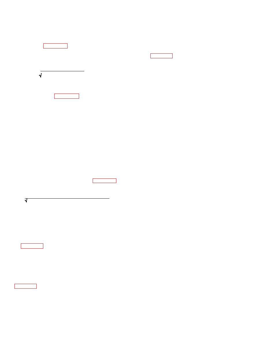
T = (/RT + Rwlre)2 + Tv2
where:
T
=
Total tension
RT =
Steady state tow resistance (Paragraph
6-3.1 and Appendix G)
Rwire =
Hydrodynamic resistance of the towline (Paragraph 6-3.2 and Table 6-1)
Tv =
Vertical component of the towline tension
RT and Rwire are computed as noted Tv is the weight of the towline forward of the catenary low point, less the slight
upward component of hydrodynamic drag on the forward half of the catenary. Location of the catenary low point and the
vertical component of the hydrodynamic drag are beyond the scope of this manual. However, errors will tend to cancel
out if Tv is assumed to be the weight (in water) of one-half the scope of the wire towline. Do not include the weight of any
chain pendant at the tow in this computation.
For example, assume that ARS 50 is towing a ship at 8 knots with a scope of 2,000 feet of 2 1/4-inch IWRC tow hawser
and 270 feet of 2 1/4-inch chain pendant at the tow. The tow provides a steady tow resistance of 60,000 pounds at 8
knots.
RT =
60,000 lbs.
Rw =
3,700 lbs (Table 6-1)
Tv =
8,143 lbs (1,000 ft. x 9.36 x .87*)
*9 36 is the dry weight of the wire from Appendix B and the .87 factor corrects dry weight for wet weight
Solving the vector diagram provides a maximum steady state tension:
T=
(60,000 + 3,700)2 + 8,1432 = 64,2181bs.
This example supports the rule of thumb that using a 10 percent factor on top of the predicted steady state tow resistance
is reasonable and accounts for the hydrodynamic resistance of the wire plus the vertical components of the catenary.
Computing the total towline tension at the tow, even with as much as 270 feet of chain pendant, shows that the total
tension is less than at the tug. Further, combinations of differentRT and different towline designs show that when Rwire is
significantly above 10 percent of RT, the catenary is very deep and tension is therefore out of the range of concern for
towline strength.
In Figure 5-2, the towing ship must supply excess thrust only equal to the horizontal component of the tension, i e., RT +
Rwire. The vertical component of towline tension Tv is absorbed by the buoyancy of the tug The additional apparent
displacement caused by Tv will require additional propulsion power, but the amount generated is so small that it can be
ignored.
5-4.2
DYNAMIC LOADS ON THE TOWLINE.
While towing at constant tug speed in a seaway the towline tension is not steady, but varies with timeas illustrated in
Te = T1 + T2 + T3
5-6
|
||
 |
||