
| Tweet |

Custom Search
|
|

|
||
 TM 11-5895-1847-12&P
OPERATOR AND UNIT MAINTENANCE
LCU 2000 GLOBAL MARITIME DISTRESS AND SAFETY SYSTEM
DESCRIPTION OF OPERATOR CONTROLS AND INDICATORS
SCOPE
The following paragraphs contain illustrations that show the location of each control and indicator for operation of
the Global Maritime Distress and Safety System (GMDSS). Each control and indicator is clearly labeled as it appears
on the equipment. Find numbers on the illustration are keyed to the tabular listing which contains the name, based on
the equipment markings, and the functional description of each control and indicator.
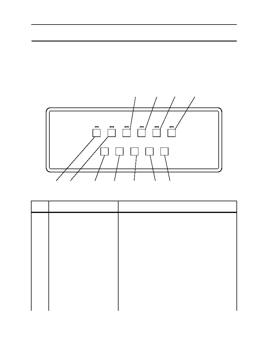
DESCRIPTION OF OPERATOR CONTROLS AND INDICATORS, WATCH RECEIVER
11
10
9
8
MF/HF DSC WATCH RECEIVER
2M
4M
8M
12M
16M
6M
2187.5
4207.5
6312
8414.5
12577
16804.5
CALL
VOL
TST
DIM
SCN
PWR
2C006-8
6
5
7
1
3
4
2
Table 1. Operator Controls and Indicators, Watch Receiver.
KEY
CONTROL/INDICATOR
FUNCTION
1
PWR
Turns power on and off to the receiver.
2
DIM
Controls illumination level for backlit keys.
3
VOL
Controls volume level.
4
SCN
Press to initiate or exit scanning mode.
5
TST
Press to initiate test mode.
6
2M
This channel cannot be deselected. GMDSS regulations require
full time scanning of 2187.5 kHz. Frequency is active when
channel key is backlit.
7
4M
Press to add or remove frequency 4207.5 kHz to scanning list.
Frequency is active when channel key is backlit.
8
6M
Press to add or remove frequency 6312 kHz to scanning list.
Frequency is active when channel key is backlit.
0006 00 1
|
||
|
||


