
| Tweet |

Custom Search
|
|

|
||
 TM 11-5895-1847-12&P
0006 00
DESCRIPTION OF OPERATOR CONTROLS AND INDICATORS, GMDSS EQUIPMENT
POWER SUPPLY
2
3
REPLACE
REGULATED LINEAR
WITH LIKE
FUSE. SEE
DC POWER SUPPLY
MANUAL
35A INTERMITTENT
15A CONTINUOUS
5
8A/115V a.c.
4A/230V a.c.
(+) 13.6V d.c. (-)
1
115V
WARNING: REMOVE ALL POWER SOURCES BEFORE
4
OBTAINING ACCESS TO TERMINALS.
NOTE:
NO USER SERVICEABLE PARTS.
QUALIFIED SERVICE PERSON ONLY.
2C006-15
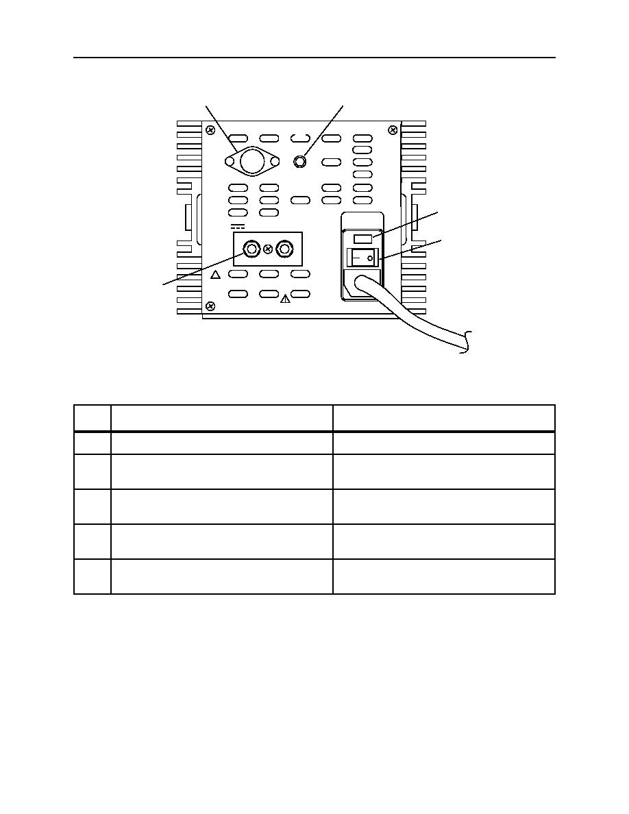
Table 10. Operator Controls and Indicators, GMDSS Equipment Power Supply.
KEY
CONTROL OR INDICATOR
FUNCTION
1
POWER SWITCH
The power switch turns the power supply on or off.
2
POWER INDICATOR LIGHT
The power indicator light, when lit, indicates that
the power supply is producing power.
3
FUSE HOLDER
The fuse holder contains the fuse for the
power supply.
4
OUTPUT TERMINALS
The output terminals provide for connection of the
power output wires to the automatic power switch.
5
VOLTAGE SELECTOR
The voltage selector switch allows the user to select
the desired input voltage; 115 volts or 220 volts.
0006 00 17
|
||
|
||


