
| Tweet |

Custom Search
|
|

|
||
 TM 11-5895-1847-12&P
0120 00
4.
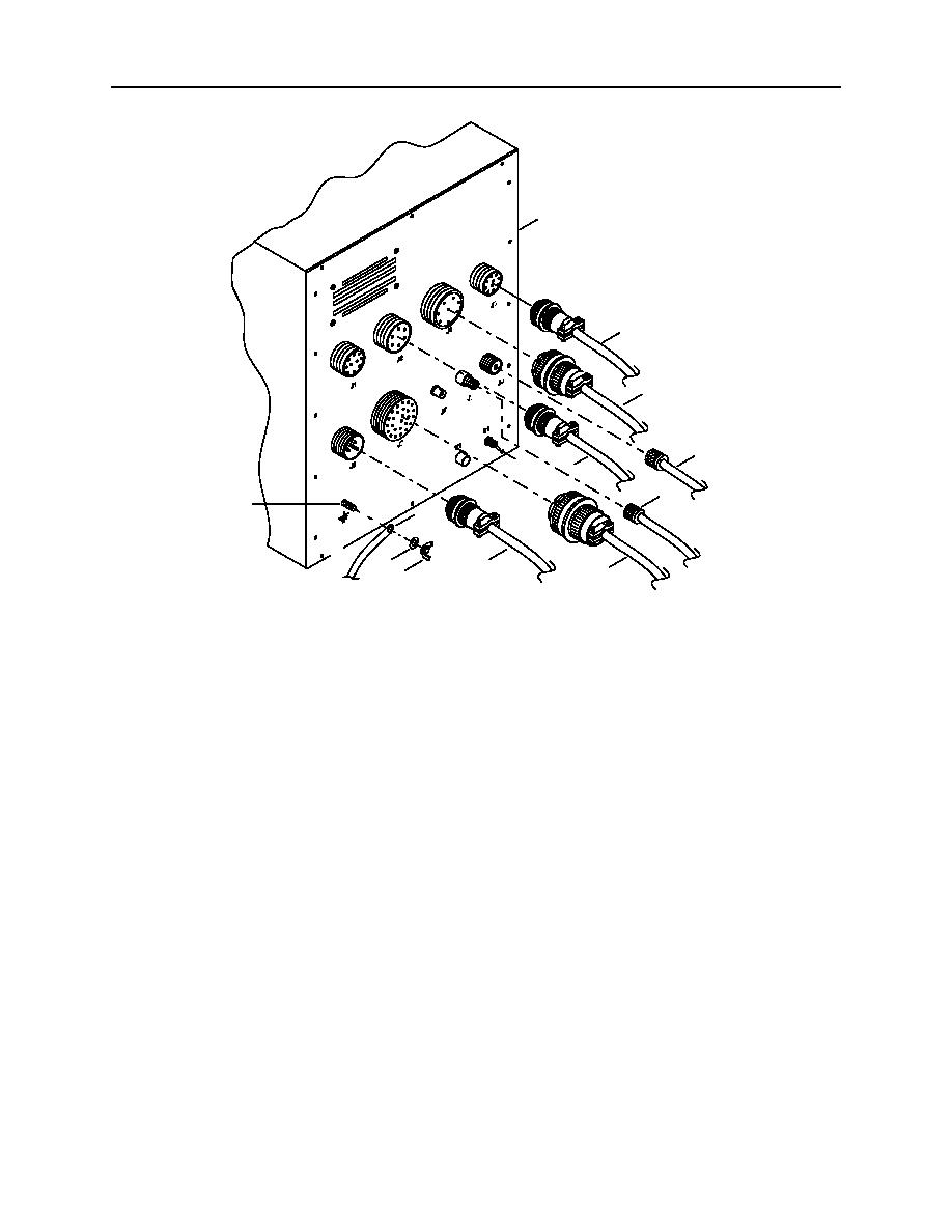
Connect ground strap (11) on ground stud (10) on back of the 9701 console (1).
1
5
4
9
2
SE
3
FU
8
10
11
6
13
7
12
2C108-1
a.
Install ground strap (11) on ground stud (10).
b.
Install washer (13) and wing nut (12) on ground stud (10). Tighten wing nut.
5.
Connect J9 antenna coaxial cable (9) to J9 antenna connector on back of the 9701 console (1).
6.
Connect J8 antenna coaxial cable (8) to J8 antenna connector on back of the 9701 console (1).
7.
Connect J6 external cable (7) to J6 receptacle on back of the 9701 console (1).
8.
Connect J5 external cable (6) to J6 receptacle on back of the 9701 console (1).
9.
Connect J4 external cable (5) to J6 receptacle on back of the 9701 console (1).
10. Connect J3 external cable (4) to J6 receptacle on back of the 9701 console (1).
11. Connect J2 external cable (3) to J6 receptacle on back of the 9701 console (1).
12. Turn power on at the GMDSS DC converter. Place the switch in the ON (up) position.
13. Turn power on at the GMDSS power supply. Place the switch in the ON (up) position.
14. Turn power on to the 9701 console (1). Place the S1 switch (2) on back of the 9701 console (1) in the ON
(up) position.
END OF WORK PACKAGE
0120 00 9/10 blank
|
||
|
||


