
| Tweet |

Custom Search
|
|

|
||
 TM 5-2805-261-13
As the flywheel spins, the magnets mounted in it spin by in
close proximity to the charge coil and trigger coil. A large
voltage is established in the charge coil and stored in the
condensers until it is released by a pulse from the trigger coil.
The ignition coils transform this stored charge into a very high
voltage which is routed to the spark plugs where it jumps the
spark plug gap and ignites the fuel air mixture.
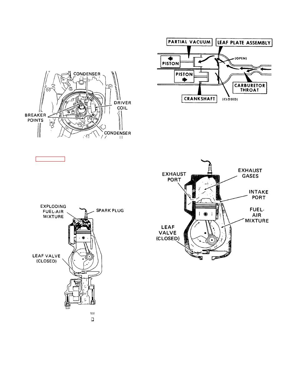
Figure 1-25. Leaf plate operation
As the piston clears the intake and exhaust ports, cast-in
deflectors on the piston head route the next charge from the
intake port and guide gases, resulting from the explosion,
through the exhaust port. Exhaust gases exit through channels
in the lower unit and gearcase. By this time the other piston
Figure 1-23. Ignition arrangement
has completed its compression stroke and the second cylinder
is fired.
NOTE
power stroke (one cylinder).
The spark ignites the combustible fuel-air mixture compressed
under the cylinder head and the resulting explosive force drives
the piston downward. Now internal crankcase pressure is
greater than carburetor pressure and the leaf valve is pushed
closed.
Figure 1-26. Routing of exhaust gases
This cycling is repeated over and over again as long as the
engine is running. At full throttle the sequential firing is so close
together as to appear simultaneous.
Figure 1-24. Power stroke
1-12
|
||
|
||


