
| Tweet |

Custom Search
|
|

|
||
 TM 5-2805-261-13
LOCATION/ITEM
ACTION
REMARKS
5-8. ENGINE REMOVAL/INSTALLATION - continued
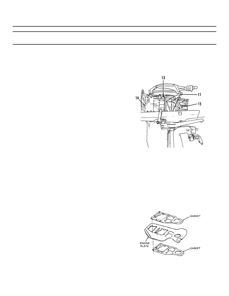
13. Shifter lock (13) and
Remove. (See page 5-20.)
shifter lock spring
14. Water indicator
Remove at fitting.
line (14)
15. Fuel return line (15)
Remove clamps and slide
off fittings.
16. Two nuts, seven 3/8
Remove.
capscrews, and two
1/2 capscrews attach-
ing engine to exhaust
housing
17. Engine.
Remove
NOTE
Pick engine straight up so the
splined connection between
crankshaft and drive shaft
will not be harmed.
18. Two gaskets and engine
Remove from exhaust
plate
housing.
Figure 5-5. Motor- starboard view
INSTALLATION
1.
Two gaskets and engine
Position on exhaust
plate
housing.
NOTE
Line up splined coupling be-
tween crankshaft and drive
shaft. Line up bolt holes
correctly.
2.
Engine
Position very carefully
on exhaust housing.
Figure 5-6. Engine plate and gaskets
5-19
|
||
|
||


