
| Tweet |

Custom Search
|
|

|
||
 TM 5-2805-261-13
LOCATION/ITEM
ACTION
REMARKS
5-8. ENGINE REMOVAL/INSTALLATION - continued
3.
Two nuts, seven 3/8
Use to attach engine to ex-
capscrews, and two 1/2
haust housing.
capscrews
4.
Fuel return line (15)
Install on fitting.
Use pliers to squeeze the two projecting ends of the
clamp. This will expand the clamp.
5.
Water indicator line (14)
Install on fitting.
6.
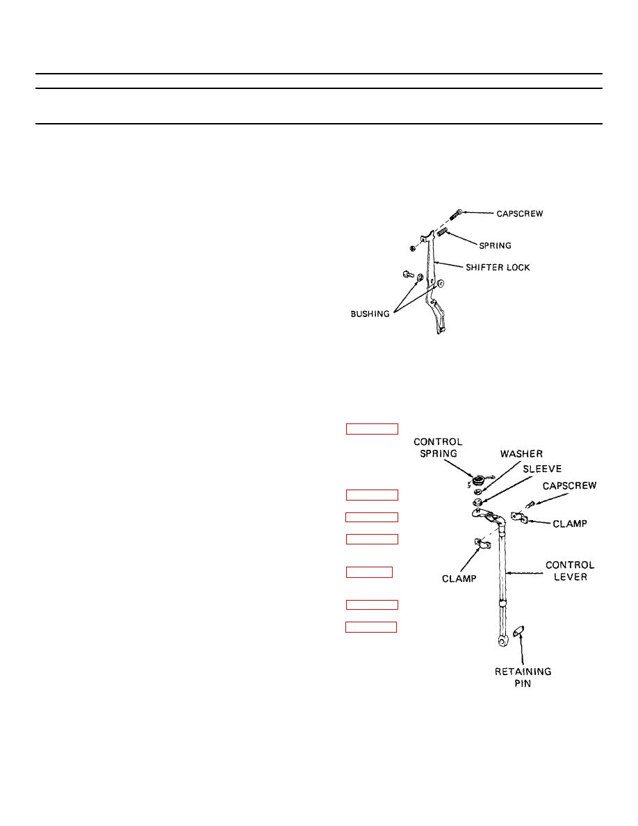
Shifter lock (13) and
Install.
shifter lock spring
7.
Throttle control lever
Place in position.
(12)
8.
Two screws and clamps
Use to secure throttle
control lever.
Figure 5-7. Shifter lock
9.
Starter mounting
Install.
Remove retaining pin from control lever. Remove
brackets (11)
grommet from lower motor cover and slide grommet
onto control lever. Install retaining pin and engage pin
in throttle control gear.
10. Ignition coils (10)
Install.
See para. 4-18.
11. Engine ground wire
Fasten to bottom
and clamp for stop
screw of port bracket.
switch leads
12. Spark plugs (9)
Install.
See para. 3-10.
13. Fuel pump (6)
Install.
See para. 4-26.
14. Auxiliary fuel filter
Install.
See para. 4-26.
(7) and fuel hoses (8)
15. Intake manifold and leaf
Install.
See para. 5-7.
valve assembly (5)
16. Carburetor (4)
Install.
See para. 4-28.
17. Armature (3)
Install.
See para. 4-16.
Figure 5-8. Throttle control lever
5-20
|
||
|
||


