
| Tweet |

Custom Search
|
|

|
||
 TM 5-2805-261-13
LOCATION/ITEM
ACTION
REMARKS
5-10. CRANKSHAFT AND PISTONS DISASSEMBLY/ASSEMBLY - continued
10. "0" ring (10)
Remove.
11. Key (11)
Remove.
12. Connecting rod cap-
Remove.
screws (12)
CAUTION
Pistons, connecting rods and
caps are matched parts and
seat with the operation of the
motor. Because of this, it is
essential to maintain their
original positions at reas-
sembly. Mark each connec-
ting rod and cap, piston, and
bearing component to assure
correct mating when they are
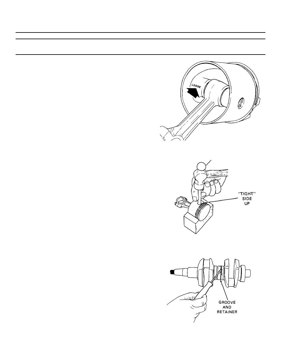
Figure 5-15. Piston - "loose" boss
correct mating when they are
reassembled. Also mark the
cylinders from which they
are removed.
13. Connecting rod caps
Remove.
14. Needle bearing
Remove.
retainers (13) and
bearings (14)
15. Piston rings (15)
Remove and discard.
16. Retaining rings (16)
Remove.
CAUTION
One piston boss is bored
larger than the other for a
loose fit. The inside of the
piston is marked with an "L"
for "loose," on the larger
Figure 5-16. Driving out the wrist pin
side. Lay the piston down
in a piston cradle with the
loose side down and drive
out the wrist pin from the
tight side.
17. Wrist pin (17)
Remove.
18. Wrist pin bearing (18)
Press out.
19. Center bearing
Lift out of groove and slide
retaining ring
aside.
20. Center bearing split
Remove from crankshaft
sleeve halves (19)
center journal.
21. Center bearing needle
Remove.
bearing retainers and
needle bearings (20).
Figure 5-17. Crankshaft center bearings
5-32
|
||
|
||


