
| Tweet |

Custom Search
|
|

|
||
 TM 55-1905-217-12
ing surfaces (journal bearing areas). The longitudinal line
connecting the lowest extrermities of all shafting journals
having the same diameter should form a continuous-
faired line when the machinery is at operating
temperature. When the shafting is correctly aligned at
rest, the bottoms of the shaft journals should be in
contact with the bearing material. The bearing clearance
at the horizontal centerline of the journal should be
equally divided.
(3) In order to obtain and maintain acceptable
alignment, the fundamentals of longe-stablished and
good practice are as follows:
(a) Each bearing shall guide and support its
proportinate share of the shafting weight and load.
(b
When shaft couplings are broken, each
overhanging shaft length will deflect from the true shaft
centerline, depending upon the amount of overhanging
shaft weight, the loading, -and the location of the bearing
supports.
(c) Alignment of sag charts have been prepared for
most vessels showing relative flange positions and the
angular slopes of shafting when the coupling 'bolts have
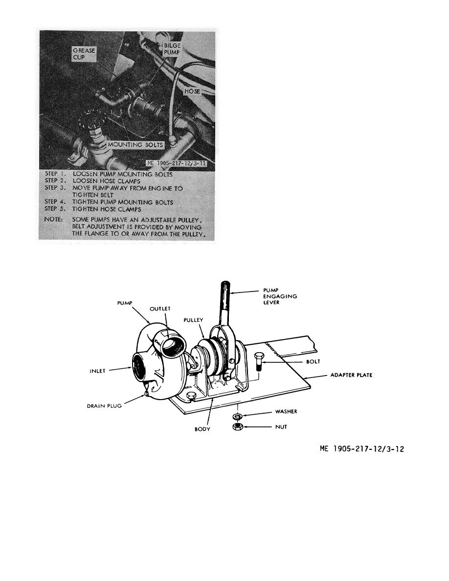
Figure 3-11. Adjusting bilge pump belt
been removed. With the bearings adjusted to obtain
these measurements, proper alignment of the shafting is
Figure 3-12. Bilge pump installation, hull numbers 8540 thru 8560 and 8580 thru 8018.
3-15
|
||
|
||


