
| Tweet |

Custom Search
|
|

|
||
 TM 55-1905-217-12
MALFUNCTION
TEST OR INSPECTION
CORRECTIVE ACTION
4.
RAMP CONTINUES TO LOWER WITH CONTROL VALVE IN NEUTRAL
Step 1. Cheek counterbalance valve.
Adjust counterbalance valve. See paragraph 4-94 or 4-96.
5.
UNUSUALLY SLOW OPERATION
Step 1. Check pump or motor.
Replace defective component (para 4-93).
Step 2. Check for restriction in line.
Clear lines (para 4-93).
Step 3. Check relief valve setting to see if it is set too low (para 4-93).
Adjust relief valve See paragraph 4-93.
6.
NOISY OPERATION OF PUMP
Step 1. Check for air in system.
Purge air from system (para 4-86).
7.
EXCESSIVE HEAT BUILDUP IN SYSTEM
Step 1. Check to see if relief valve is leaking at high pressure.
Adjust relief valve. See paragraph 4-93.
8.
LOSS OF OIL
Step 1. Check for ruptured line
Replace line.
Step 2. Check ramp locking system two-way valve for external or internal leakage (hull numbers 8540
thru 8566 and 8580 thru 8618).
Tighten connections and replace defective parts (para 4-97).
SECTION VII. RADIO INTERFERENCE SUPPRESSION
4-15. General Methods Used to Attain Proper
4-18. Testing of Radio Interference Suppression
Suppression
Components
Essentially, suppression is attained by providing a low
Test the capacitors for leaks and shorts on a capacitor
resistance path to ground for the stray currents. The
tester; replace defective capacitors. If test equipment is
methods used include shielding wires, grounding the
not available and interference is indicated, isolate the
frame with bonding straps, and using capacitors and
cause of interference by the trial-and-error method of
resistors.
replacing each capacitor in turn until the cause of
interference is located and eliminated.
4-16. Radio Interference Suppression Components
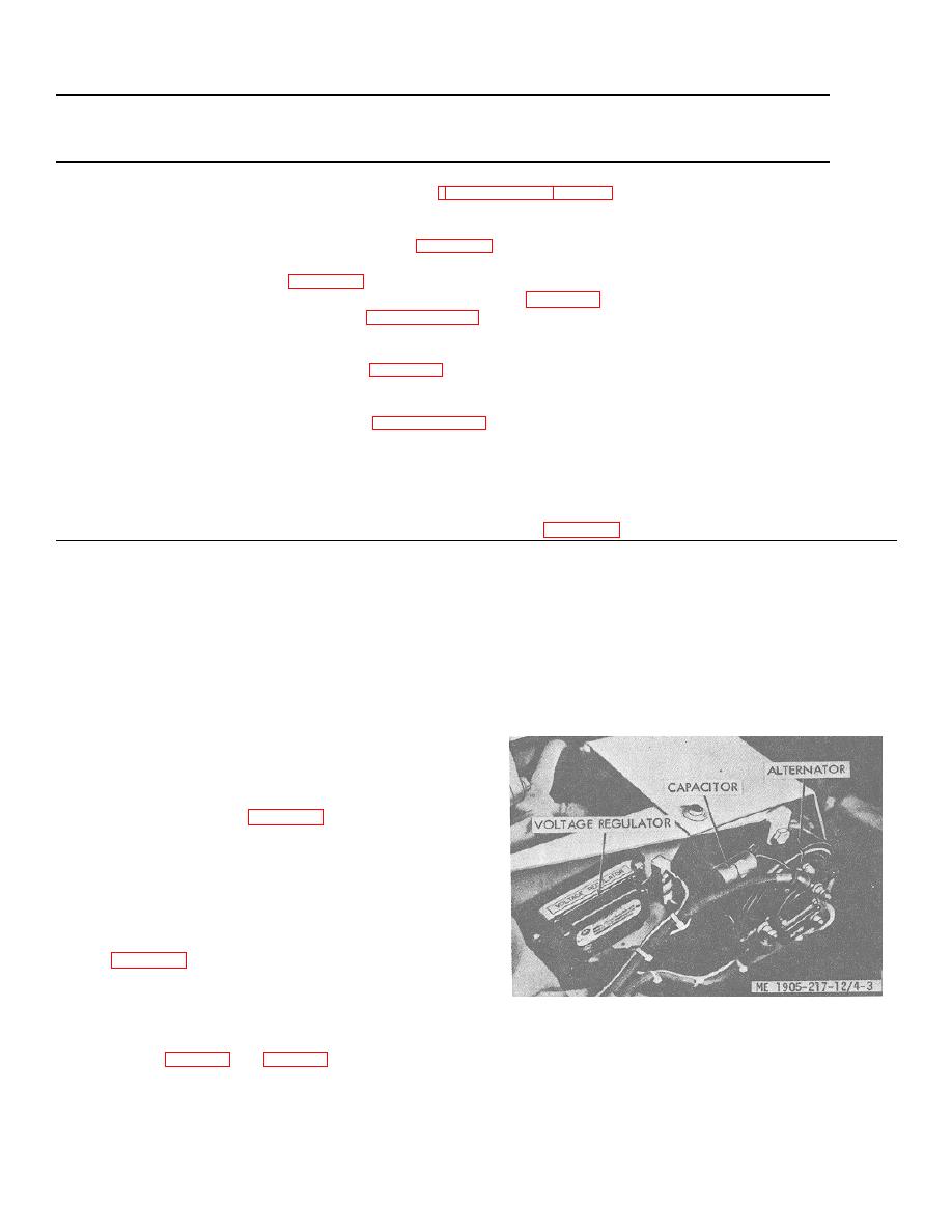
a. Primary Suppression Components. The primary
suppression components are those whose primary
function is 'to suppress radio interference. These
components are identified in figure 4-3.
b. Secondary Suppression Components. These
components have radio interference suppression
functions which are incidental or secondary to their
primary function.
4-17. Replacement of Suppression Components
Refer to figure 4-3 and replace the radio interference
suppression components.
Figure 4-3. Interference suppression components.
SECTION VIII. ENGINES
two six-cylinder diesel engines in a side-by-side
arrangement coupled to a transfer gear and mounted on
a. Description. Model 12005A (starboard) and
a steel base.
12006A (,port) twin units each consist of
4-13
|
||
|
||


