
| Tweet |

Custom Search
|
|

|
||
 TM 55-1905-217-12
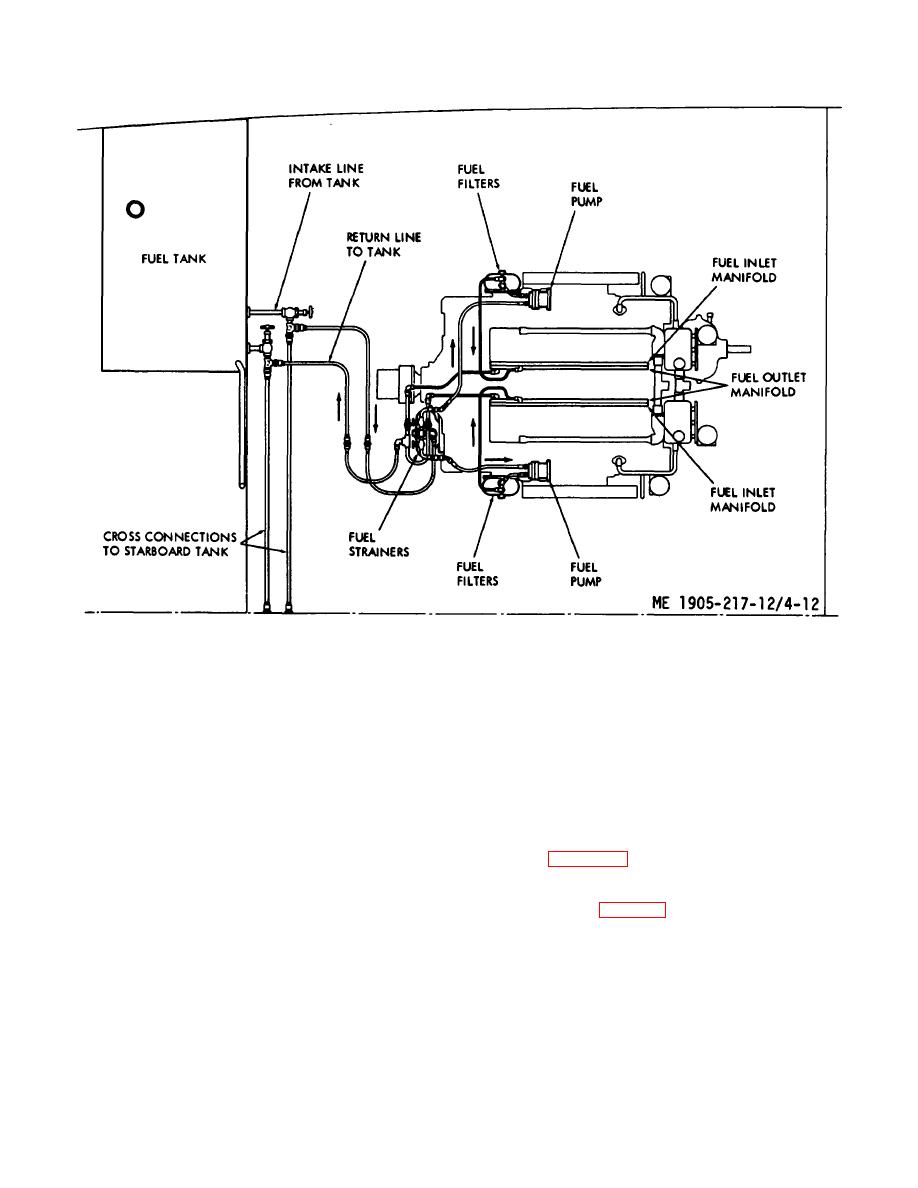
Figure 4-12. Fuel system diagram.
ring together (do not remove clamping ring from case).
old elements and gaskets. Using new elements of the
Care must be taken not to lose or damage case gasket.
type and number specified on shell and the new gaskets
(d) Loosen stuffing box nut.
provided in the element cage, reassemble the filters.
(e) Unscrew element and knife assembly
With engine running, check for leaks.
c. Primary Fuel Strainer (hull numbers 8540 thru
by turning right (left-4and thread) until it is free.
8560 and 8580 thru 8618). Refer to figure 84 for strainer
(2) Inspection and service.
(a) Inspect edge of cleaning knife for
servicing instructions.
wear.
(b) Inspect element for wear caused by
4-28. Fuel Injectors
a. Description. Fuel injectors are installed as
cleaning knives or damage which will allow dirt to pass
through the filtering screen.
shown in figure 4-18. They are mounted in the cylinder
(c) Submerge element assembly in fuel oil
head with their spray tips projecting slightly below the top
and wash with soft lint-free cloth or soft hair brush. Do
of the inside surface of the combustion chambers.
b. Removal (fig. 4-14).
not use wire brush or scraper. Exercise care not to allow
dirt to enter inside of element.
(1) Remove the valve rocker cover.
(d) Reassemble strainer assembly and
(2) Remove the fuel pipes from both the
place in service.
injector and the fuel connectors.
b. Fuel Filters. With engine stopped, loosen top
(3) Install clean shipping caps on the injector
retaining bolt and remove filter shells and elements.
fuel inlet and outlet and on the fuel connectors..
Wash shells in clean fuel and discard
4-19
|
||
|
||


