
| Tweet |

Custom Search
|
|

|
||
 idle-range rpm, and drive ratio. The maximum engine
(4) If, after making the preceding checks, the
speed, not shown on the identification plate, is stamped
governor fails to control the engine properly, the governor
on the option plate attached to the valve rocker cover.
should be removed and reconditioned.
b. Checking Governor Operation.
c
Removing the Governor (fig. 4-18, 4-19, and 4-20).
(1) Governor difficulties are -usually indicated
by speed variations of the engine; however, it does not
(1) Disconnect the linkage attached to the
necessarily mean that all such speed fluctuations are
governor control levers.
caused by the governor. Therefore, when improper
(2) Remove the breather tube.
speed variations appear, the engine should be checked.
(3) Remove four screws and lockwashers and
(2) Check the engine to be sure all cylinders
lift the governor cover and gasket from the governor
are firing. If any cylinder is not firing, replace the injector
housing.
(4) Refer to figure 4-20 and disconnect the fuel
(3) Check for bind that may exist in the
rod from the differential lever.
governor operating mechanism or in the linkage between
(5) Remove the four bolts and the separate
the governor and the control tube. With the fuel rod
cover from the weight housing.
connected to the injector control tube lever, the
'(6) Remove two governor-to-cylinder head
mechanism should be free from bind throughout the
bolts.
entire travel of the injector racks. If friction exists in the
(7) Move the upper end of the control housing
mechanism, it may be located and corrected as follows:
away from the cylinder head and free the lower end from
(a) If an injector rack sticks or moves too hard, it
the weight housing.
may he due to the injector hold-down clamp being too
(8) Use tool J4242, to remove the six governor
tight or improperly positioned. To correct this condition,
weight housing-to-blower bolts; then withdraw the
loosen the injector clamp, reposition, and tighten to 20-
housing from the blower.
d Installing the Governor.
25 ft-lb torque.
(b) A binding injector may result from internal dirt
(1) Affix anew gasket to the governor weight
accumulation, defective plunger and bushing, or a bent
housing. Start the splined end of the weight shaft in the
injector rack. A defective injector must be replaced.
upper blower rotor and position the housing against the
blower end plate.
(c) An injector rack may bind as the result of an
improperly positioned rack control lever. Loosen the
control rack adjusting screws.
If this relieves the bind, relocate the lever on the control
tube and position the rack as outlined in paragraph 4-1.
(d) The injector control tube may bind in its support
brackets, thus preventing -free movement of the injector
racks to their no-fuel position due to tension of the return
spring. This condition may be corrected by loosening and
realining the control tube supporting brackets. If the
control tube support brackets were loosened, realined
and tightened, the injector racks must be repositioned as
outlined in paragraph 4-31.
(e) A bent injector control tube return spring may
cause friction in the operation of the injector control tube.
If the spring has been bent or otherwise distorted, install
a new spring. Check for bind at the pin which connects
the fuel rod to the injector control tube lever; replace the
pin if necessary.
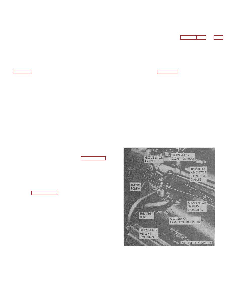
Figure 4-18. Removing the governor.
4-23
|
||
|
||


