
| Tweet |

Custom Search
|
|

|
||
 TM 55-1905-217-12
(11) Attach the fuel rod to the injector control
tube lever with a pin and cotter pin.
(12) Place a new gasket on the governor control
housing and mount the governor cover on the housing
with the pin on the throttle shaft registering with the
machined slot in the differential lever.
(13) Install
the
four
cover
screws
with
(14) Connect throttle linkage.
(15) Attach the breather tube to the governor
housing.
(16) Adjust the governor and position the injector
rack control levers as instructed in paragraph 4-31.
4-31.
Governor
and
Injector
Rack
Control
Adjustments
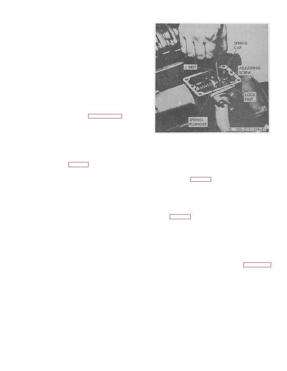
Figure 4-21. Adjusting Gap.
a. Governor Gap Adjustment. With the engine at
operating temperature, adjust the governor gap as
b. Positioning Injector Rack Control Levers.
follows:
(1) With the engine stopped, remove the two
The position of the injector racks must be correctly set in
attaching bolts and withdraw the governor high speed
relation to the governor. Their position determines the
spring retainer cover (13, fig. 4-20).
amount of fuel injected into each cylinder and ensures
(2) Back out the buffer screw (7) until it extends
equal distribution of the load. Adjust the No. 1 injector
approximately 5/8 inch from the locknut.
rack control lever (fig. 4-22) first to establish a guide for
(3) Start the engine and ,loosen the idle speed
adjusting the remaining injector rack control levers.
adjusting screw locknut and adjust the idle screw (1) to
obtain the desired idle speed.
(1) Disconnect any linkage attached to the
Hold the screw and tighten the locknut to retain the
governor speed control lever.
adjustment. The recommended idle speed is 550 rpm.
(4) Stop the engine and remove the governor
(2) Loosen the idle speed adjusting screw
cover and lever assembly.
locknut (fig. 4-20) and back out the idle speed adjusting
(5) Remove the valve rocker cover.
screw until 1/2 inch of the threads project from the
(6) Remove the fuel rod (17) from the
locknut %-hen the nut is against the high speed plunger.
differential lever and the injector control tube lever.
(7) Check the gap between the low speed
(3) Loosen all of the inner and outer injector
spring cap and the high speed spring plunger with gage
rack control lever adjusting screws. Be sure all of the
(0.170 in.) J5407 as shown in figure
control levers are free on the injector control tube.
(8) If required, loosen the locknut and turn the
gap adjusting screw until a slight drag is felt on the gage.
(4) Move the governor speed control lever to
(9) Hold the adjusting screw and tighten the
the maximum speed position as shown in figure 4-22.
locknut.
Hold the lever in that position with light finger pressure.
(10) Recheck the gap and readjust if necessary.
Turn the inner adjusting screw on the No. 1 injector rack
(11) Install the fuel rod between the governor
control lever down until a slight movement of the control
and injector control tube lever.
tube is observed or a step up in effort is noted. This will
(12) Install the governor cover and lever
place the No. 1 injector rack in the full-fuel position. Turn
assembly.
the outer adjusting screw down until it bottoms lightly on
the injector control tube. Then, alternately tighten both
the inner and outer adjusting screws.
4-26
|
||
|
||


