
| Tweet |

Custom Search
|
|

|
||
 TM 55-1905-217-12
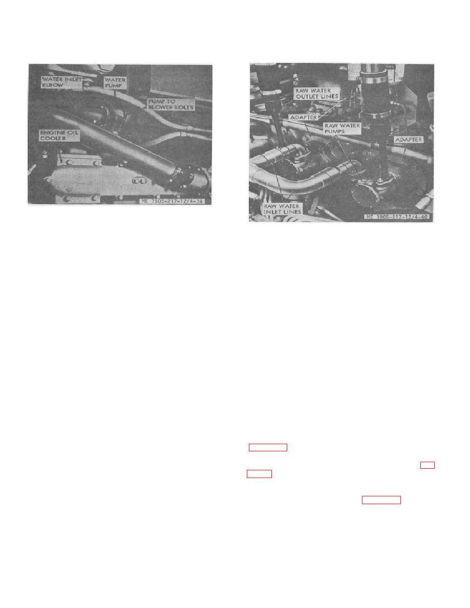
Figure 4-39. Fresh water pump mounting.
Figure 4-40. Raw (sea) water pump mountings.
SECTION XIII. ELECTRICAL SYSTEM INSTRUMENTS AND GAGES
b. In-Vessel Testing (Hull numbers 8500 thru 8519
4-47.
General
and 8520 thru 8539). The following test procedures may
be performed to determine the condition of the alternator
The electrical system (1-3 and 1-4 )includes two 70-amp,
and regulator while still in the vessel.
24-volt alternators, one alternator mounted on the
inboard engine of each propulsion unit. Four 6-volt
batteries, connected in series to provide 24-volt current,
NOTE
are contained in the battery box located aft in the engine
room. The alternators and batteries provided electrical
When making the alternator system test, the batteries
power to operate all lights and electrical accessories on
must be in good condition and fully charged.
the landing craft and for the electric starters which are
mounted on the outboard engines of each propulsion
CAUTION
unit.
Do not under any circumstances, short FIELD terminal of
4-48.
alternator to ground. Do not disconnect regulator while
alternator is operating. Do not disconnect alternator
a. Description. One 70-amp, 24-volt alternator is
output lead from alternator while the alternator is
belt driven from the inboard engine crank-shaft pulley.
operating.
The electrical circuit of the alternator uses six silicon
diodes in a full wave rectifier circuit. Since the diodes will
(1) Check voltage across auxiliary terminal
pass current from the alternator to the battery or load but
will not pass current from the battery to the alternator, the
voltmeter. Correct voltage is 0.2 volt. If the voltage
alternator does not require the use of cutout relay. A
exceeds this value, the isolation diode is defective (fig.
voltage regulator is the only control required.
4-41.3).
(2) Place jumper wire across oil pressure
switch on propulsion unit to short out switch. Check
CAUTION
voltage across auxiliary terminal (fig. 4-41.1) and
Disconnect battery cables when working on alternator or
voltage is 1.8-to 2.5-volts. This test evaluates field
regulator.
circuit. If voltage at
4-43
|
||
|
||


