
| Tweet |

Custom Search
|
|

|
||
 TM 55-1905-217-12
(2) Remove access cover.
(3) Remove attaching clamp at rear of panel
and remove instrument or gage.
c. Installation. Install instrument or gage in reverse
order of removal.
4-53.
Tachometers and Tachometer Drives
a. General. Tachometers are mounted in the pilot
house instrument panel, one for each engine. The
tachometer drives are mounted on the transmission oil
pumps at the rear of each engine.
b. Removal..
(1) Refer to paragraph 4-52 for removal of
tachometers from the instrument panel.
(2) Refer to figure 4-46 or 4-47 for removal of
tachometer drive.
4-54.
Warning Lights and Sending .Units
a. General. Sending units (lobe oil pressure switch
and water temperature switch) are installed on each
engine to provide warnings to be indicated on the engine
alarm panel (fig. 2-8.1 or 4-45) if the engine lubricating oil
pressure is too low or if the engine water temperature is
too high. To protect the circuit and switches, the circuit
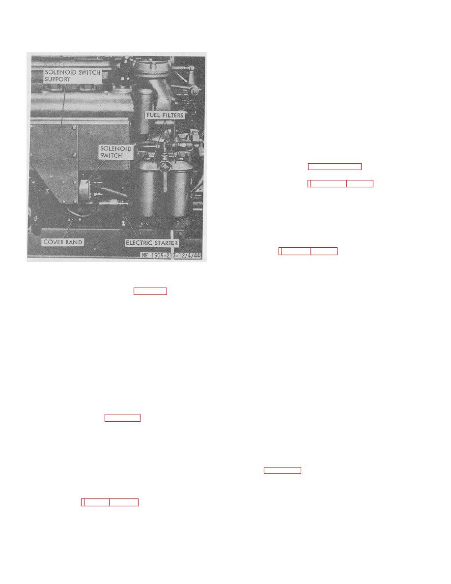
Figure 4-44. Electric starter and solenoid switch.
is not energized until the fuel oil pressure switch is
closed. The fuel oil pressure switches are installed in the
c. Electric Starter Removal (fig. 4-44).
fuel oil manifolds which are a part of the engine cylinder
(1) Disconnect negative lead at battery.
head casting.
(2) Remove and tag solenoid switch leads.
b. Testing.
(3) Remove solenoid switch and switch
(1) With engine stopped, place a jumper wire
support.
across the fuel oil pressure switch terminals.
(4) Remove and tag starter leads.
(5) Turn fuel filter valve lever to shut off the
NOTE
forward filter. Drain filter and remove the shell and
element.
On hull number 8520 thru 8560 and 8580 thru 8618,
(6) Remove the three bolts and lockwashers
there are two fuel oil pressure switches in the fuel oil
securing the starting motor to the flywheel housing and
manifold of each inboard engine. Place the jumper wire
remove starting motor from the engine.
only on the switch with four leads. The switch with two
d. Starting Motor Installation. Reverse removal
leads is not included in the alarm circuit.
procedures, using a serviceable starting motor.
(2) Move the engine alarm indicator switch
4-51.
Battery Cables (fig. 3-10)
(on distribution panel) to the ON position. The lamp
should light for the circuit being tested. If further testing
a. Removal. Disconnect and remove the negative
is required, refer to higher echelon.
lead, then disconnect and remove the positive lead.
b. Installation. Reverse procedure above.
4-55.
Navigational and Utility Lights
4-52.
Instruments and Gages
Refer to figures 2-2 (hull numbers 8520 thru 8539), or 2-
3 (hull numbers 8540 thru 8560 and 8580 thru 8618) for
a. General. Instruments and gages are located on
identification and location of lights.
panels in the pilot house and in the engine room.
(1) Remove plastic panel cover.
4-52
|
||
|
||


