
| Tweet |

Custom Search
|
|

|
||
 TM 55-1905-217-12
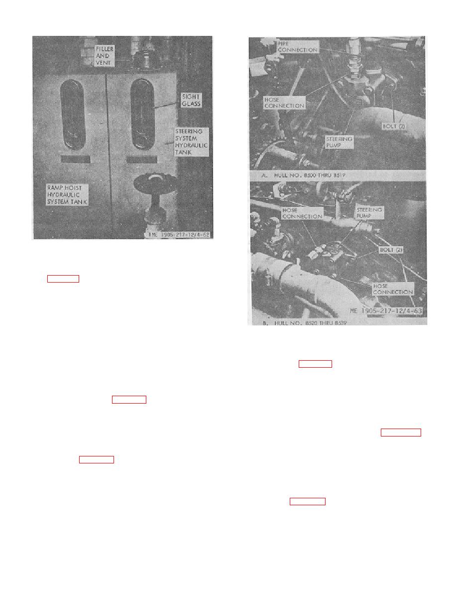
Figure 4-62. Steering and ramp hoist hydraulic. system
tanks.
(2) Remove Inlet and outlet connections from
pump (fig. 4-63).
(3) Remove two attaching bolts and remove
pump.
NOTE
Steering pump)s for hull numbers 8500 thru
Figure 4-63. Hydraulic steering pump.
8519 and hull numbers 8520 thru 8560 Land
8580 thru 8618 are similar but not identical.
nicks in rods call be removed by light stoning.
c. .Installation. Install pump In reverse order of
removal. Accurate positioning of the adapter gear on the
(1) Close hall valves for cylinder to be
pump shaft is necessary for proper alinement of drive
removed.
components.
(2) Disconnect cylinder hoses at cylinder.
(3) Remove pins at cylinder ends and remove
4-79. Steering Cylinders (fig. 4-64)
cylinder.
a General. Steering cylinders are mounted in the
d . Installation. Install cylinder in reverse order of
lazarette with the rod ends attached to rudder post arms.
removal.
There are two ball valves in the lazarette for each
e . Rudder Stop Adjustment Refer to figure 4-66 for
cylinder. The valves can be closed to isolate a cylinder in
rudder stop locations.
case of failure.
4-80. Steering System Valve Adjustments (Hull
b. Service (fig. 4-65). Steering cylinders normally
Numbers 8500 thru 8519)
live no trouble other than excessive leakage-internal or
a. General. Before adjusting the relief valve or the
external. Tightening the "V" rod packing assembly will
double over-center valve, place a 0-2000 psi pressure
usually stop external leakage. Should leakage persist,
gage in the line between the flow control valve and the
examine the rod for scoring and/or replace seals Mild
helm unit. See figure 1-9.
scores or
4-68
|
||
|
||


