
| Tweet |

Custom Search
|
|

|
||
 TM 55-1905-217-12
4-81. Steering System Valve Adjustments (HuIH1
Numbers 8520 thru 8560 and 8580 thru 8618)
See figure 1-9 or 1-10 for valve locations in system.
a. Relief Valve. This valve is to be set for a
maximum system pressure of 1050 psi. Refer to
b. Flow Divider. This valve is a preset priority type
supplying a constant 2 gpm to the helm unit. Excess oil is
bled back to the reservoir.
c. Counterbalance Valves (2). The counterbalance
valves induce an artificial pressure on the low pressure
side of the steering cylinders to prevent the rudder from
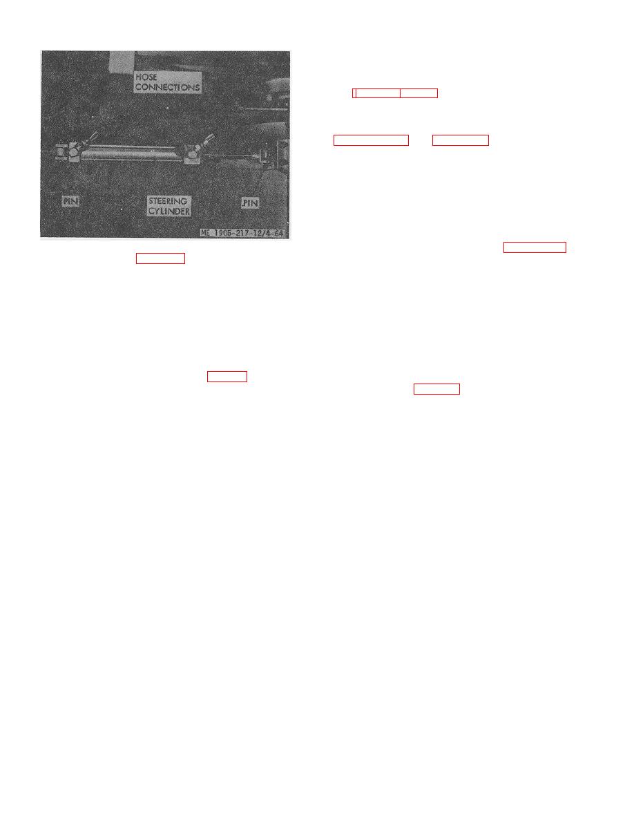
Figure 4-64. Steering cylinder removal
running ahead of the pumps. See figure 4-70. These
b. Relief Valve (fig. 4-67). Adjust by putting the
valves are set at 1,000 psi.
helm hardover in either direction with engines running (1
pump only supplying system). Remove cap from the
4-82. Helm Unit and 'Steering Wheel
relief valve, loosen nut, and back off screw until it no
a. General. The helm unit and other valves control
longer bears on the spring. Hold the helm in a hardover
the direction and volume of flow of the hydraulic oil in the
position and slowly turn down screw until the pressure
steering system. The helm unit directs the oil to one side
gage reads 1,500 psi indicating that the valve is relieving
or the other of the cylinders and limits the flow according
at 1,500 psi. Lock this setting with nut and replace cap.
to the speed at which the steering wheel is turned. In
c. Flow Control Valve. This valve is preset at the
event of pump failure the helm unit will also act as a
factory and cannot be adjusted.
pump when turned manually.
d. Double Over-Center Valve (fig. 4-68). Adjust
with the screws. Loosen nuts and back off screws until
b. Removal (fig. 4-71).
they no longer bear on springs. Rotate the helm and
(1) Remove steering wheel.
slowly turn down screws until the pressure gage reads
(2) Remove access covers in pilot house panel.
150 psi indicating that a pressure of 150 psi is required to
(3) Clean the four tube connections at helm unit
open the over-center valve and start motion in the
with a solvent-wetted cloth so that contamination will not
cy1.inders. This operation must be performed 'first in one
enter the system.
direction, adjusting one side of the over-center valve,
(4) Disconnect the four tubes or hoses as
then repeated for the other side. With the above setting
applicable from the helm unit
the over-center valve will resist a kick-back force from
(5) Remove four mounting bolts and remove
the rudders equal to the force exerted by the cylinders at
helm unit.
1,500 psi. This adjustment must be made with the
c. Installation. Install helm unit in reverse order of
cylinders at mid-stroke and the craft motionless in the
removal.
water so that no load is applied to the cylinders.
4-69
|
||
|
||


