
| Tweet |

Custom Search
|
|

|
||
 TM 55-1905-217-12
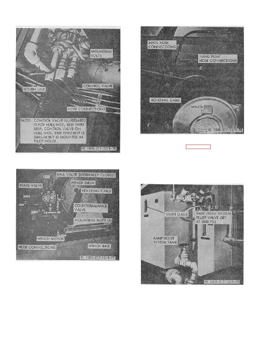
Figure 4-78. Ramp winch, hull numbers 8520 thru 8559.
b. Adjustment. See figure 4-79. If adjustment is
required proceed as follows:
(1) Install 3,000 psi pressure gage, with shutoff
Figure 4-76. Ramp hoist control valve.
valve, in system at tee fitting or port in relief valve.
(2) Wrap several turns of heavy manila rope
around winch drum and belay running end to prevent
operation of winch.
Figure 4-77. Ramp winch, hull numbers 8500 thru 8519.
4-93. Relief Valve, Ramp Hoist System (Hull
Numbers 8500 thru 8519)
Figure 4-79. Ramp hoist system relief valve, hull
a. General. The main system relief valve is used
numbers 8500 thru 8519.
for system protection. It has an operating range of 1500-
,to 3000-Ipsi, but is normally adjusted to 2000, psi.
4-77
|
||
|
||


