
| Tweet |

Custom Search
|
|
|
|
||

|
||
 TM 55-1905-217-12
pump is belt-driven from the inboard engine of the
starboard propulsion unit. See figure 4-83. See figure 3-12
for bilge pump installation on hull numbers 8540 thru
8560 and 8580 thru 8618. These pumps have a single
moving part, the impeller and shaft assembly. Only one
grease cup requires attention. See lubrication order.
The grease cup provides lubrication for the bronze
bushing on impeller end of shaft. Ball bearing at other
end of shaft is grease-pack and requires no attention.
b. Packing Gland Adjustment. Do not tighten more
than necessary to stop leakage of water. Repack when
necessary with 1/8-inch metallic string packing.
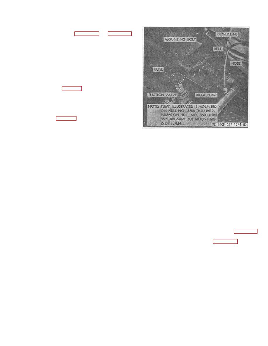
c. Pump Removal (fig. 4-83).
(1) Close primer line valve and suction valve.
(2) Loosen hose clamps and slide hoses away
from pump.
(3) Loosen mounting bolt nuts and remove belt.
(4) Remove mounting bolts and remove pump.
d. Disassembly (fig. 4-84).
(1) Remove the pump housing from the clutch
body by removing the six attaching nuts and, washers.
Remove carefully to protect gasket.
Figure 4-83. Bilge pump removal
(2) Remove end nut and clamp washer from
the clutch end of unit and press or drive out the shaft and
f.
Reassembly.
impeller assembly from ball bearing and while supporting
(1) Reassemble in reverse order of
the clutch body. When the shaft is being removed, look
disassembly.
for spacing shim before pulling the shaft through the
(2) After 'pump has been assembled and nuts
packing and gland as shim will be damaged if left on the
tightened, check clearance between face of impeller and
shaft.
housing. The clearance shall be 0.010-to 0.012iinch and
(3) To remove ball bearing, first remove the
is controlled by the number of gaskets between housing
packing and gland. Remove the bearing snap retaining
and body. Check the clearance between the back face
rings and insert a brass drift through the -housing end to
of the impeller and the clutch body. The clearance shall
the inner race of the bearing. Tap the drift lightly and
be 0.010-to 0.015-inch and -is controlled by shim
remove the bearing. The impeller should not be
thickness at shaft shoulder.
removed from the shaft.
(3) Shaft bearings are packed and do not
e. Inspection and Repair.
require lubrication.
(1) Inspect impeller housing and pressure plate
g. Installation. Install pump in reverse order of
for excessive wear.
removal.
(2) Inspect shaft for wear, scores, or burrs.
Inspect impeller for wear or damage.
4-102. Strainers and Lines
(3) Inspect packing glands for serviceability.
Locations of lines and strainers are indicated in, figure 2-14.
(4) Remove burrs by careful stoning or lapping.
No service is required except inspection of strainers
Round out nicks and uneven edges on impeller. Fit new
to be sure they are free from debris. Figure 4-85 depicts
parts to replace defective items. If impeller is damaged,
a typical foot valve installation used on hull -numbers
a new shaft assembly is required.
8540 thru 8560 and 8580 thru 8618.
4-103. Fuel Oil Heat Exchangers Hull 8540 Thru
8618)
a. General. The fuel oil heat exchangers are
vertically mounted in the raw water cooling lines -for
each engine muffler. The exchangers cool the surplus
fuel returning from the outlet side of the injector back to
the fuel tank.
4-82
|
||
|
||


