
| Tweet |

Custom Search
|
|

|
||
 TM 55-1905-217-34
If after several attempts, the spray tip cannot be positioned satisfactorily check the assembly of the entire
injector.
i. Installation.
(1) Test the injector (para (d) above).
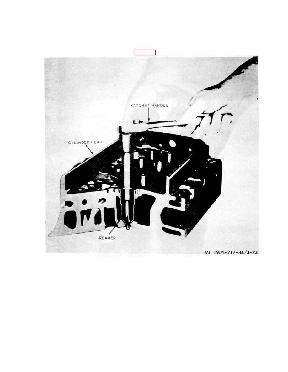
(2) Ream the beveled seat of the injector tube in the cylinder head. Pack the flutes of the reamer with
grease to retain the carbon removed from the tube (fig. 3-23).
Figure 3-23. Reaming seat of injector tube in cylinder head
CAUTION
Exercise care to remove only the carbon when reaming the injector tube seat
so that the proper clearance can be maintained between the injector body
and the cylinder head.
(3) Refer to TM 55-1905-217-12, para 4-28 for installation of the fuel injectors.
3-3. Fuel Pump
a. Removal. Refer to TM 55-1905-217-12, para 4-29, for removal of the fuel pump.
b. Disassembly. With fuel pump removed from the engine and mounted in the holding fixture refer to figure
3-24 and disassemble the pump as follows:
(1) Remove the eight cover bolts, then withdraw the pump cover from the pump body. Use care not to
damage the finished faces of the pump body and cover.
(2) Withdraw the drive shaft, drive gear and gear retaining ball as an assembly from the pump body.
(3) Press the drive shaft just far enough to
Change 1 3-26
|
||
|
||


