
| Tweet |

Custom Search
|
|

|
||
 TM 55-1905-217-34
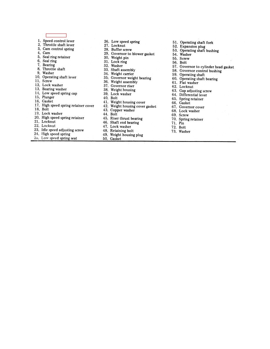
Key to Figure 3-25
(b) Loosen speed control lever bolt, and lift the speed control lever (1) from the throttle shaft.
(c) Remove the tapered pin from the throttle shaft lever. Lift the lever and the seal ring retainer from the throttle
shaft. Withdraw the throttle shaft from the cover.
(d) Remove the cam retainer and plain washer from the cam pin. Lift the cam off the pin.
(e) Remove the seal ring (6) from the governor cover.
(f) Wash the cover assembly (containing needle bearings) thoroughly in clean fuel oil and inspect the needle
bearings for wear or damage. If the bearings are satisfactory for further use, removal is necessary.
(g) If needle bearing removal is necessary, place the inner face of the cover over the opening in the bed of the
press. Place remover J 21967 on top of the bearing and under the ram of the press; then press both bearings out of
the cover.
(2) Governor control housing:
(a) Place the control housing in a soft jawed vise.
(b) Remove two bolts (18) and withdraw the high speed spring retainer cover (17).
(c) Loosen the lock nut (21) with tool J 5345-5. Remove the high speed spring retainer (20), idle adjusting
screw (23), high speed spring (24), spring plunger, low speed spring (26) spring seat (25), and spring cap (14) as an
assembly.
(d) Remove the spring retainer (65) and washer, then lift the differential lever (64) from the pin of operating
shaft lever (10).
(e) Remove the expansion plug (52) out of the lower end of the control housing.
(f) Remove the bearing retaining screw (11), flat washer (61), and lock washer.
(g) Support the control housing. Press the operating shaft (59) from the operating fork using a brass rod.
Withdraw the operating shaft, operating lever (10) and bearing as an assembly from the control housing.
(h) Support the operating shaft and lever on bed of press. Press the shaft from the operating lever and bearing
with a brass rod.
(3) Governor weight housing:
(a) Place the weight housing in a soft jawed vise. Remove the plug (49) and gasket (50).
(b) Straighten the tang of the lock washer and remove the bearing retaining bolt (48).
(c) Thread a 5/16 inch-24 x 3 inch bolt into the tapped end of the weight shaft (33). Support the weight housing
(38) on the bed of the press and press the shaft from the bearing.
(d) Slide the riser thrust bearing (45) and governor riser (37) from the shaft.
NOTE
This bearing is especially designed to absorb thrust loads; therefore, looseness between
the mating parts does not indicate excessive wear.
(e) Remove the bearing (46) from the weight housing.
(f) Mark the weights (36) and carrier (34) with a center punch for identification, also note position of the thin
washers (32) between the weights so that the parts can be replaced in their original position.
3-31
|
||
|
||


