
| Tweet |

Custom Search
|
|

|
||
 TM 55-1905-217-34
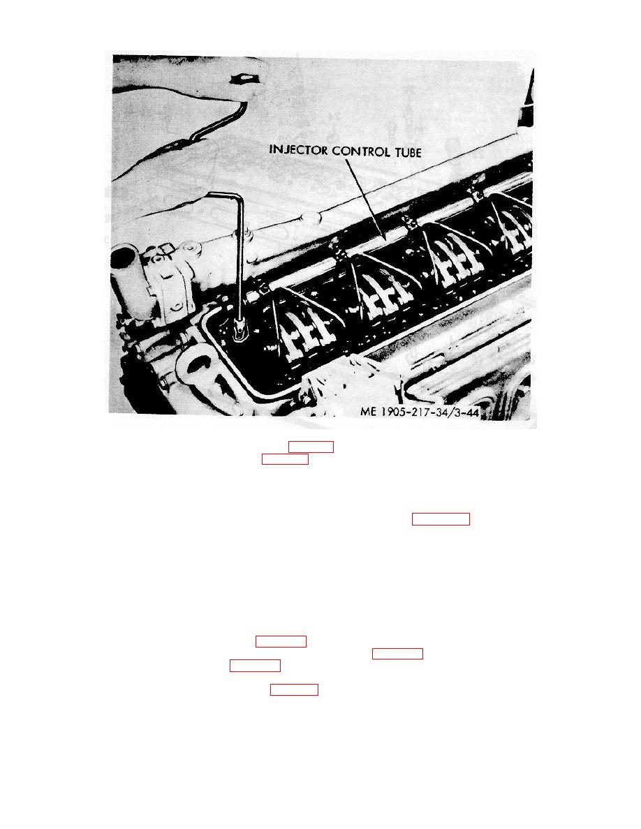
Figure 3-44. Injector control tube and cylinder head mounting nuts and bolts, removal and installation.
(6) Remove fuel injectors and connectors (para 3-4).
(7) Remove the governor assembly (para 3- 4).
(8) Loosen the two bolts directly below each lifter bracket which attach the balance weight cover and
flywheel housing to the front and rear end plates.
(9) Remove the four bolts that secure the lifter brackets to the balance weight cover and flywheel
housing.
(10) Remove the cylinder head mounting nuts and bolts as shown in figure 3-44.
(11) Insert lifting hooks into the lifting bracket eyes and, with a hoist, lift the cylinder head evenly off the
cylinder head studs.
CAUTION
Do not set the cylinder head with the bottom face down on bench as this will
damage the cam followers and injector spray tips will be damaged.
b. Disassembly. If a cylinder head was removed for inspection and possible repair or replacement,
remove the following parts:
(1) Fuel injectors, if not already removed. Refer to TM 55-1905-217-12, paragraph 4-28, for removal.
(2) Fuel oil connectors. Refer to TM 55-1905-217-12, paragraph 4-28 for removal.
(3) Valve and injector rocker arms (para 3-14).
(4) Cam followers, spring retainers, push rods, and springs (para 3-14).
(5) Valves and valve springs (para 3-15).
(6) Water manifold. Refer to TM 55-1905-27-12, paragraph 4-43, for removal.
(7) Remove the valve spring locks (1, fig. 3-45), retainers (2), springs (3), shouldered washer (4), and
valves (5) from the head.
3-63
|
||
|
||


