
| Tweet |

Custom Search
|
|

|
||
 TM 55-1905-217-34
NOTE
The push rod spring seat retainer remains in the cylinder head.
(2) Cleaning and Inspection.
(a) When any appreciable change in the injector timing or exhaust valve clearance occurs during engine operation,
remove the cam followers and their related parts and inspect them for excessive wear. This change in the injector timing
or valve clearance during engine operation can usually be detected by excessive noise at idle speed.
(b) After the cam followers and their associated parts are removed, clean all of the parts thoroughly with solvent FED.
SPEC. PD- 680, and dry them with compressed air.
(c) Inspect the push rods and push rod spring seats for wear.
(d) The purpose of a push rod spring is to maintain a predetermined load on the cam follower to insure contact of the
cam roller on the camshaft lobe at all times. Check the push rod spring load whenever the cam followers and their related
parts are removed for inspection.
(e) The push rod spring is made of wire .177 inch in diameter and has a free length of 2 5/8 inches. Replace the
spring when a load of less then 172 pounds will compress it to a length of 2 1/8 inches.
(f) Examine the cam follower bores in the cylinder head to make sure they are clean, smooth, and free of score marks
to permit proper functioning of the cam followers. Clean up any existing score marks.
(g) The diameter of a cam follower is 1.060 inches to 1.061 inches, an the clearance between the cam follower and
d
cylinder head bore with new parts is .001 inch to .003 inch. With used parts, a maximum clearance of .006 inch is
allowable.
(h) The cam rollers must turn smoothly and freely on their pins, and the rollers must be free from flat spots or scuff
marks. If the rollers do not turn freely, or have been scored or worn flat, then examine the cams on which they operate. If
the cams are excessively worn or damaged, replace the camshaft.
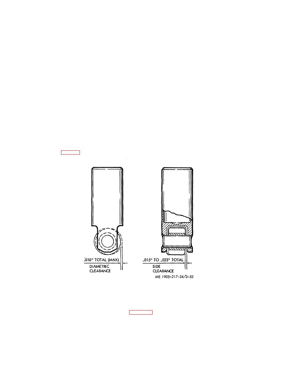
(i) Measure the total clearance between the roller bushing and pin, crosswise of the pin, and, if the bushing is worn to
the extent that more than .010 diametric clearance exists, install a new cam roller and pin, which are serviced as a set, in
the follower assembly. Also, check the total side clearance between the roller and follower; this clearance must be .015
inch to .023 inch (fig. 3- 53).
Figure 3-53. Cam roller wear and clearance diagram.
(j) Cam followers that are stamped with the letter "S" on the pin, roller and follower body are equipped with an
oversize pin and roller. An oversize roller and pin are available as a set for service. DO NOT attempt to bore out the legs
of a standard cam follower for an oversize pin. The same clearances apply to either a standard or oversize cam follower
assembly.
(3) Cam Follower Roller and Pin Replacement. Replace a cam follower roller, using fixture J 5840, as follows:
(a) Lock the fixture securely in a vise as shown in figure 3-54. Then, place the cam follower in the groove in the top of
the fixture with the follower pin resting on top of the corresponding size plunger in the fixture.
3-72
|
||
|
||


