
| Tweet |

Custom Search
|
|

|
||
 TM 55-1905-217-34
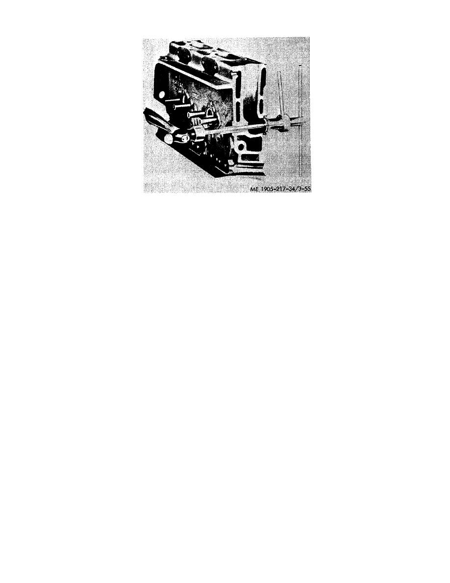
Figure 3-55. Valve seat insert, removal.
(11) Place the collet of tool J 4824-01 inside the valve insert so that the bottom of the collet is flush with bottom of
the insert.
(12) Hold the collet handle and turn the T handle to expand the collet cone until the insert is held securely by the
tool.
(13) Insert the drive bar of the tool through the valve guide.
(14) Tap the drive bar once or twice to move the insert about 1/16 inch away from its seat in the cylinder head.
(15) Turn the T handle to loosen the collet cone and move the tool into the insert slightly so that the narrow flange
at the bottom of the collet is below the valve seat insert.
(16) Tighten the T handle and continue to drive the insert out of the cylinder head.
b. Cleaning and Inspection.
(1) Valve Springs.
(a) Clean the spring with fuel oil and dry it with compressed air. Then inspect the spring for pitted or fractured
coils.
(b) Use spring tester J 9666 and an accurate torque wrench to check the spring load.
NOTE
The valve springs should be replaced when a load less than 135 pounds will compress the
spring to 1 49/64 inches.
(2) Exhaust Valves.
(a) Carbon on the face of a valve indicates blowby due to a faulty seat. Black carbon deposits extending from the
valve seats to the valve guides may result from cold operation due to light loads or the use of too light a grade of fuel.
Rusty brown valve heads with carbon deposits forming narrow collars near the valve guides evidence hot operation due to
overloads, inadequate cooling, or improper timing which results in carbonization of the lubricating oil.
(b) Clean the carbon from the valve stems and wash the valves with fuel oil. The valvestems must be free from
scratches or scuff marks and the valve faces must be free from ridges, cracks, or pitting. If necessary, reface the valves or
in- stall new valves. If the valve heads are warped, replace the valves.
(3) Exhaust Valve Guides.
(a) Clean the inside diameter of the valve guides with brush J 5437. This brush will remove all gum or carbon
deposits from the guides, including the spiral grooves.
(b) Inspect the valve guides for fractures, chipping, scoring, or excessive wear. C eck the valve-to-guide
h
clearance, since worn valve guides may eventually result in improper valve seat contact. If the clearance exceeds .006
inch, replace the valve guides.
(4) Exhaust Valve Seat Insert. Inspect the valve seat inserts for excessive wear, pitting, cracking or and improper
seat angle. The proper angle for the seating face of both valve and insert is 30
.
c. Reconditioning Valve and Valve Seat.
(1) Reface an exhaust valve which is to be reused, if necessary. The edge of the valve at the valve head must not
be less than 1/32 inch in thickness after refacing.
(2) Before installing either a new or used valve, examine the valve seat insert in the cylinder head for proper valve
seating. The proper angle for the seating face of both the valve and valve insert is 30
.
(3) The angle of the valve seat insert must be exactly the same as the angle of the valve face so as to provide
proper seating of the valve.
(4) When a new valve seat insert is installed or an old insert is reconditioned, the work must be done with a
grinding tool.
(5) The eccentric grinding method for reconditioning valve seat inserts is recommended. This method produces a
finer, more accurate finish since only one point of the grinding wheel is in contact with the valve seat at any time. A
micrometer feed permits feeding the grinding wheel into the work .001 inch at a time.
3-75
|
||
|
||


