
| Tweet |

Custom Search
|
|

|
||
 TM 55-1905-217-34
(6) The eccentric valve seat grinder set, tool J 8165, used to recondition or grind the valve seat inserts consists of:
(a) Grinder, tool J 8165-1.
(b) Dial gage, tool J 8165-2.
(c) Pilot, tool J 8165-3.
(d) Grinding wheel (15 , tool J 8165-4.
)
(e) Grinding wheel (30, tool J 8165-5.
)
(f) Grinding wheel (60, tool J 8165-7.
)
(7) Grind the inserts as follows:
(a) Use the 30 grinding wheel on the valve seat.
(b) Use the 60 grinding wheel to open the throat of the insert.
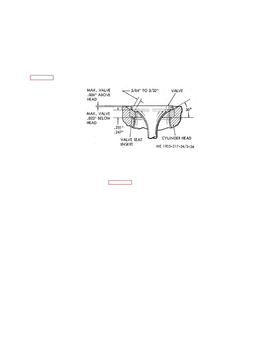
(c) Grind the top surface of the insert with the 15 wheel to narrow the width of the seat to the dimensions shown
in figure 3-56. Adjust the 30 face of the insert, relative to the center of the valve face, with the 15 and 60 grinding
wheels.
Figure 3-56. Relationship between exhaust valve, insert, and cylinder head.
CAUTION
Do not permit the grinding wheel to contact the cylinder head when grinding the
insert.
(8) The maximum allowable limits the exhaust valve should protrude beyond the cylinder head (when the valve is
closed) for the valve seat inserts is shown in figure 3-56. Grinding will reduce the thickness of the valve seat insert, which
will allow the valve to recede into the head. These maximum allowable limits are also shown and if the grinding operations
reduce the valve seat thickness so that the valve recedes beyond these limits, the valve seat insert must be replaced.
(9) After the grinding has been completed, clean the valve seat insert thoroughly with fuel oil and blow it dry with
compressed air. Set the dial indicator J 8165-2 in position and rotate it to determine the concentricity of each valve seat
insert relative to the valve guide. Total runout should not exceed .002 inch. If a runout of more than .002 inch is indicated,
check for a bent valve guide before regrinding the insert.
(10) When a valve seat insert runout within the desired limits is obtained, determine the position of the contact area
between the valve and the valve seat insert in the following manner:
(a) Apply a light coat of Prussian blue, OF a similar paste, to the valve seat insert.
(b) Lower the stem of the valve in the valve guide and bounce, but do not rotate the valve on the insert. This
procedure will indicate the area of contact on the valve face. The most desirable area of contact is at the center of the
valve face.
(11) Dress the grinding wheel to obtain the proper seat angle. After the valve seat inserts have been ground and
inspected, clean the cylinder head thoroughly before installing the valves.
d. Reassembly and Installation.
(1) Exhaust Valve Guide. Turn the cylinder head right side up on the work bench and install the valve guide as
follows:
(a) Insert the internally threaded end of the valve guide in the J 9530 valve guide installing tool.
CAUTION
Be sure to use the correct tool to avoid damage to the valve guide, and to locate the
valve guide to the proper dimension above top of head.
(b) Position the valve guide squarely in the bore in the cylinder head and tap the installing tool gently to start the
guide in place. Then, drive the guide in until the tool contacts the cylinder head.
NOTE
Do not use the valve guides as a means of turning the cylinder head over or m handling the
cylinder head.
NOTE
Service replacement valve guides are completely finish reamed during manufacture and,
therefore, do not require reaming after installation.
(2) Exhaust Valve Seat Insert. Great care must be used during the installation of at valve seat insert since this part
has a press fit in the cylinder head. Install the insert in the following manner:
(a) Wash the cylinder head with fuel oil and dry it with compressed air.
(b) Clean the valve insert counterbore in
3-76
|
||
|
||


