
| Tweet |

Custom Search
|
|

|
||
 TM 55-1905-217-34
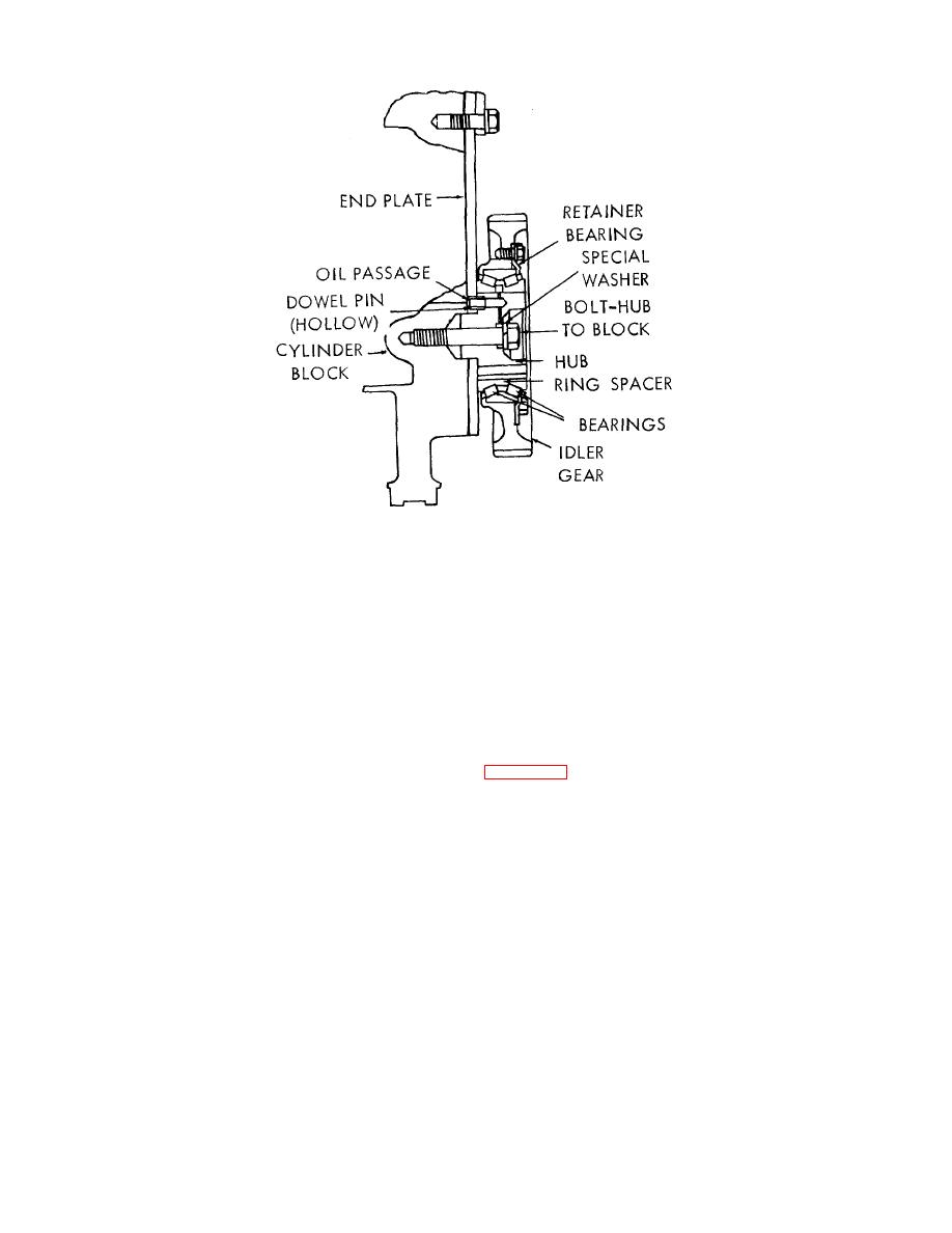
Figure 3-57. Idler gear assembly, cross section view
(2) The inner races of the idler gear bearing are pressed onto the gear hub and, therefore, do not rotate since the
hub is doweled to the end plate and bolted to the cylinder block and also bolted to the flywheel housing. A spacer, on
current bearings, separates the two bearing inner races. No spacer was used on early design bearings.
(3) The bearing outer race has a light press fit in the idler gear and is held against a flanged lip inside the idler gear
on one side and by a retainer secured tightly with six bolts on the other side.
(4) A right-hand helix gear with "L" timing marks is provided for left-hand rotation engines, and a left-hand helix gear
with "R" timing marks is provided for right-hand rotation engines.
(5) An idler gear hole spacer (dummy hub) is used on the side opposite the idler gear. NO gasket is used between
the idler gear hub or dummy hub and the flywheel housing. The flywheel housing bears against the inner races of the idler
gear bearing and also against the dummy hub. Three self-locking bolts and steel washers are used to attach the flywheel
housing at the idler gear and dummy hub locations. The washers seat in 7/8" spot faces at the flywheel housing attaching
bolt holes, thus preventing oil leakage at these locations.
b. Removal. (Flywheel Housing Removed).
(1) Remove the hub to cylinder block bolt and washer (Figure 3-57) and withdraw the assembly from the cylinder
block rear end plate.
3-78
|
||
|
||


