
| Tweet |

Custom Search
|
|

|
||
 TM 55-1905-217-34
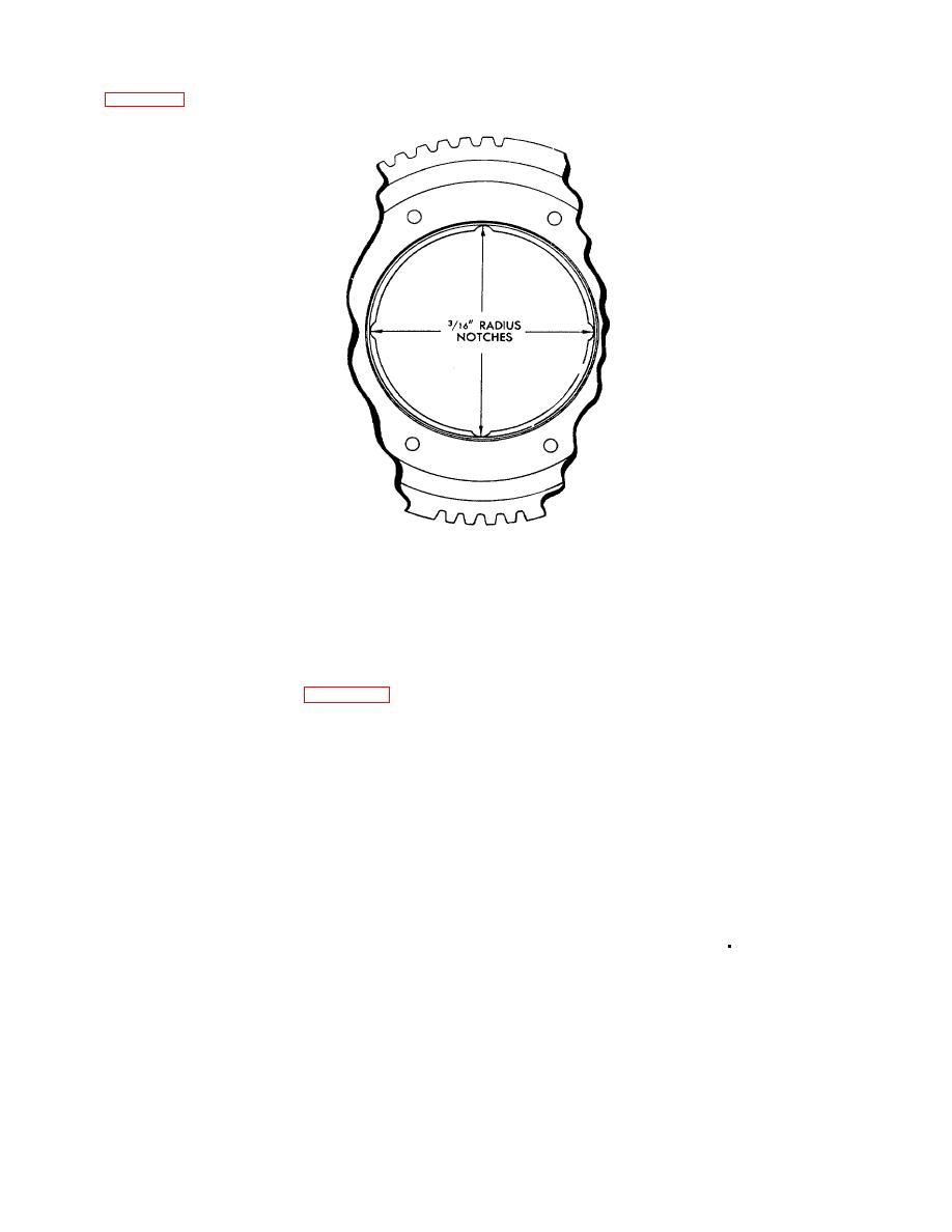
(g) Four equally spaced notches, approximately 3/16" radius, may be filed or ground on the shoulder of the gear as shown
in figure 3- 63. Use care to avoid damage to the bore in the gear, break all sharp edges, and clean all chips and dirt from
the gear.
Figure 3-63. Location of notches in idler gear.
d. Cleaning and Inspection.
(1) Clean the idler gear, hub, and bearing components in cleaning solvent (FED. SPEC. PD-680) and dry with
compressed air.
(2) Inspect bearings carefully. Wear, pitting, scoring or flat spots on rollers or races are sufficient cause for
rejection and the bearing assembly must be replaced.
(3) Check the idler gear hub and spacer. The three flywheel housing mounting bolt holes were not drilled through on
early design hubs and spacers. Consequently, these hubs must be inspected to assure that no chips or foreign material is
deposited in the holes so as to cause interference with the flywheel attaching bolts.
(4) Examine the gear teeth for evidence of scoring, pitting and wear. If severely damaged or worn, replace the gear.
Also, inspect other gears in the gear trains.
e. Reassembly. Refer to figure 3-59 and assemble bearing components in their original positions (refer to
identification marks made during disassembly) as outlined below:
(1) Support the idler gear, shoulder down, on the bed of an arbor press and start the outer bearing race squarely
into the bore of the gear. Then, press the bearing race tight against the shoulder of the gear, using a steel plate between
the ram of the press and the bearing race.
(2) Support one bearing cone, numbered side down, on bed of arbor press and lower the idler gear and bearing cup
assembly down over the bearing cone.
(3) Lay spacer ring on face of bearing cone.
(4) Place second bearing cone, numbered side up, in idler gear and bearing cup assembly and against spacer ring.
(5) Then, position the idler gear hub over the bearing cones so that the oil hole in the hub is 180 o from the gap in
the spacer ring. To assemble the early design bearing in which the bearing cones are held together by a snap ring, use the
following procedure:
(a) Place first bearing cone on work bench and place idler gear shoulder face up, over cone.
(b) Lift both idler gear and bearing cone together, being careful that the rollers do nor escape their retainer , and
invert the gear and cone and place them over the second cone.
(c) Press the upper bearing cone down by hand, then rock it to engage the snap ring in the grooves of the cones.
Do not lift the gear and bearing assembly from the work bench until the snap ring is engaged .
(d) Position notches of bearing cones so they are together.
(e) Then, position the idler gear hub over the bearing cones so the oil hole in the hub is 180 from the notches in
the cones.
(6) Press the hub into the idller gear bearing cones, while rotating the gear (to seat rollers properly between cones)
until the face of the hub which will be adjacent to the cylinder block end plate is flush with the corresponding face of the
bearing cone. The bearing cones should be supported so as not to load the bearing rollers during this operation.
(7) Prior to installing and securing the bearing retainer, check the preload of the bearing assembly as outlined
below.
f. Checking Bearing Preload.
(1) he rollers of the bearing are loaded between the bearing cup and bearing cones in accordance with design
requirements to provide a rigid idler gear and bearing assembly. As the bearing cones are moved toward each other in a
tapered roller bearing assembly, the rollers will be more tightly held between the cones and cup. In the idler gear bearings,
a slight pre-load is applied by means of a selected spacer ring between the bearing cones, to provide rigidity of the gear
and bearing assembly when it is mounted on its hub.
3-85
|
||
|
||


