
| Tweet |

Custom Search
|
|

|
||
 TM 55-1905-217-34
This method of pre-loading is measured, in terms of "pounds-pull", by
the effort required at the outer diameter of the gear to turn the bearing
cup in relation to the bearing cones.
(2) Any time an idler gear assembly has been removed from
an engine for servicing or inspection, while performing engine
overhaul or other repairs, the pre-load should be measured as part of
the operation.
(3) After the idler gear, hub, and bearing are assembled
together, the bearing should be checked to ascertain that the gear
may be rotated on its bearing without exceeding the maximum torque
specifications, nor be so loose as to permit the gear to be moved in
relation to the hub by tilting, wobbling or shaking the gear.
(4) If the mating crankshaft and camshaft or balance shaft
gears (depending upon engine rotation) are not already mounted on
the engine, the torque required to rotate the idler gear may be
checked by mounting the idler gear in position on the engine, using a
steel plate 4" square and 3/8" thick against the hub and cone as
outlined below.
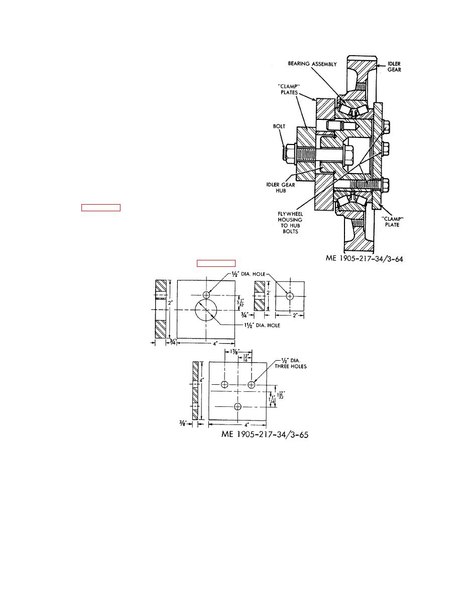
(5) However, if the crankshaft and camshaft gears are on the
engine, a suitable fixture, which may be held in a vise, may be made
as shown in figure 3-64. Three plates, a 1/2"-13 x 2 3/4" bolt and a
plain washer are used with a 1/2 "-13 nut and plain washer for
mounting. One of the plates is used to take the place of the flywheel
housing, and the other two plates, the cylinder block. "Engine-
mounted" conditions are simulated by tightening the nut to 80-90 lb-ft
Figure 3-64. Fixture for testing bearing pre-load
torque and tightening the three plate-to-hub attaching bolts to 25-40
lb-ft torque. The components of the fixture may be made from steel
stock in accordance with the dimensions shown in figure 3- 65.
Figure 3-65. Plates for bearing test fixture.
3-86
|
||
|
||


