
| Tweet |

Custom Search
|
|

|
||
 TM 55-1905-217-34
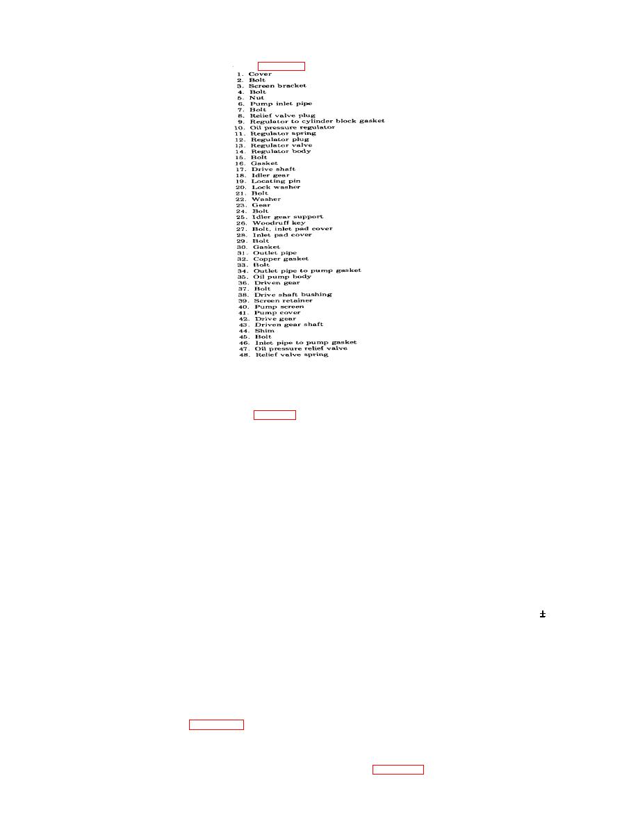
Key to figure 3-70.
NOTE
If shims were used between the pump mounting feet and bearing caps, note their location
and save for installation.
b. Disassembly.
(1) Remove the oil pump inlet pipe (6, fig. 3-70) with the screen cover and mounting brackets.
(2) Remove the oil pressure regulator assembly (10) and the oil pump outlet pipe (31) as an assembly from the
pump body (35).
(3) Remove valve plugs (8) and copper gaskets (32) from each side of the pump body, and jar the relief valve parts
(47 and 48) from the pump body.
(4) Remove the pump driven gear (36) from the driven gear shaft (43).
(5) Straighten the lip of the lock washer (20) and unscrew the bolt (21) thus freeing the idler gear (18).
(6) Clamp the pump body, drive shaft, and gear assembly in a bench vise. Pull the drive driven gear (23) from the
outer end of the pump drive shaft using a gear puller.
(7) Remove the woodruff key (26) from the drive shaft and withdraw the shaft and driven gear (36) from the pump
body.
(8) Unscrew the bolt (24) and remove the idler gear support (25) from the pump body.
(9) If the drive gear (42) is to be replaced, position the gear and shaft assembly on the bed of an arbor press with
the long end of the shaft extending down through the slot in the bed plate and with the gear resting on the plate. Place a
short (3 or 4 inches long) 1/2 inch round steel rod on the end of the shaft and press the shaft from the gear.
c. Cleaning, Inspection and Repair.
(1) Wash all parts in solvent (FED. SPEC PD-680) and dry them with compressed air.
(2) Examine the gear cavity in the pump body and the drive shaft bushings. If the driven gear bushings are worn,
replace the bushings Service replacement bushings in the driven gears must be reamed after assembly to 0.625 0.0005
inches. If the gear housing is scored, a new pump body and cover should be installed.
NOTE
If the pump is to operate efficiently, the gears should have a free-running fit (no perceptible
looseness) in the pump housing.
(3) If the gear teeth are scored or worn, install new gears. The use of excessively worn gears will result in low
engine oil pressure which, in turn, may lead to serious damage throughout the engine.
(4) Inspect the pressure relief valve and its seat in the pump body. If necessary, install new parts.
(5) Check the pressure relief valve spring. Its free length is 2 23/64 inches and a load of 48 to 53 pounds should
compress it to 1.5076 inches. If less than 48 pounds compresses it to this length, replace it.
(1) Insert woodruff key (26) in the keyway of drive shaft (17) and apply a light coat of engine oil on the shaft. Start
the shaft squarely into the bore of the gear (42) and press the shaft into the gear.
NOTE
The gear must be positioned on the shaft as shown in figure 3-71.
3-97
TM 55-1905-217-34
|
||
|
||


