
| Tweet |

Custom Search
|
|

|
||
 TM 55-1905-217-34
(9) Check the connecting rod bushings for indications of scoring, overheating, or other damage.
Bushings that have overheated may become loose and creep together, thus blocking off the supply of
lubricating oil to the piston pin and spray nozzle.
(10) Since it is subjected to downward loading only, free movement of the piston pin is desired to secure
perfect alignment and uniform wear. Therefore, the piston pin is assembled with a full floating fit in the
connecting rod and piston bushings, and with relatively large clearances. Worn piston pin clearances up to .010
inch are satisfactory. Measure the outside diameter of the piston pin to determine the amount of wear. The
diameter of a new standard size piston pin is 1.4996 inches to 1.5000 inches.
(11) The inside diameter of a new connecting rod bushing is 1.5015 inches to 1.5020 inches. The
specified clearance between the piston pin and connecting rod bushings is .0015 inch to .0024 inch with new
parts.
e. Reassembly. With the connecting rod clamped in holder J 7632 as outlined above, install the new
bushings as follows:
(1) Connecting Rod Bushing Installation.
(a) Start one of the bushings straight into the bore of the connecting rod.
NOTE
The bushing joint must be toward the top of the connecting rod.
(b) Insert bushing installer J 1513-6 in the bushing. Then, insert handle J 1513-2 in the installer
and drive the bushing in until the flange of the installer bottoms on the connecting rod.
(c) Turn the connecting rod over in the holder, aline the bore in the rod with the hole in the base
of the tool, and install the second bushing in the same manner.
(2) Ream Bushings in Connecting Rod. Service replacement bushings must be reamed to size, using
tool set J 2686-02, in the following manner:
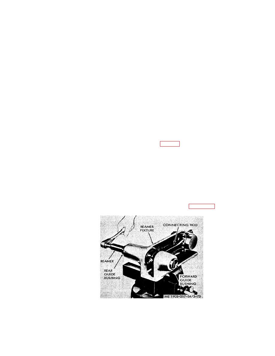
(a) Clamp reaming fixture J 1686-9 in a bench vise (fig. 3-73).
(b) Place the large end of the connecting rod over the arbor of the fixture and tighten the
connecting rod cap nuts to 60-70 Ib-ft torque.
(c) Slide forward guide bushing J 1686-11 into the front guide boss with the pin end facing out.
(d) Aline the upper end of the connecting rod with the opening in the reaming fixture.
(e) Install rear guide bushing J 1686-5 on reamer J 1686-10, and insert the reamer and bushing
through the rear guide boss of the fixture.
(f) Turn the reamer in a clockwise direction only, when reaming or withdrawing the reamer.
(g) Remove the reamer and the connecting rod from the fixture, blow out the chips, and
measure the inside diameter of the bushings. The inside diameter of the bushings must be 1.5015 inches to
1.5020 inches to provide a clearance of .0015 inch to .0024 inch with a new piston pin.
(3) Install Spray Nozzle in Connecting Rod.
(a) Start the spray nozzle, with the holes positioned as shown in figure 3-74, straight into the
counter bore in the top of the connecting rod.
Figure 3-73. Reaming piston pin bushings in connecting rod.
3-101
|
||
|
||


