
| Tweet |

Custom Search
|
|

|
||
 TM 55-1905-217-34
b. Removal.
(1) Drain oil from transfer gear and flywheel housings.
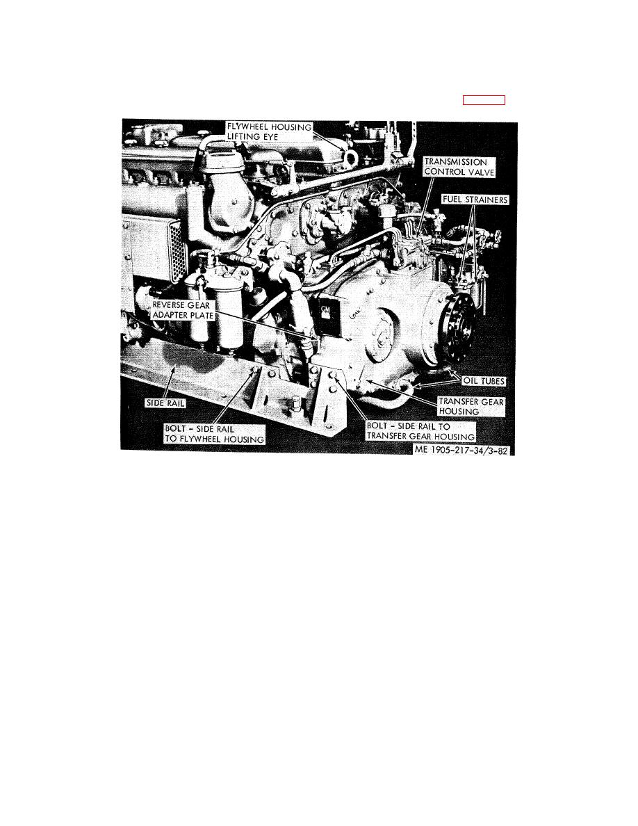
(2) Disconnect the two transfer gear housing to reverse gear housing oil tubes (fig. 3-82).
Figure 3-82. Transfer gear housing and flywheel housing, removal and installation.
(3) Remove control valve from power transfer gear housing.
(4) Disconnect fuel lines and remove fuel strainer mounting bracket.
(5) Remove the four side rail to transfer gear housing bolts and lock washers on each side.
(6) Loosen the front motor support to side rail bolts.
(7) Attach a sling and chain hoist to the lifter bracket at the tip of each engine flywheel housing. Remove
the two side rail to flywheel housing bolts at side of each flywheel housing. Raise the rear end of engines just enough to
ease load of transfer gear from the engine side rails: then, place wood blocks beneath each flywheel housing to support
engines.
NOTE
When blocking is in place and load of engines is resting thereon, the space between
the mounting boss at each side of transfer gear housing and end of side rails should be
approximately 1/8 inch.
(8) Thread an eyebolt into one of the tapped holes provided at each side of gear housing, and attach a
chain from hoist to each eyebolt to support transfer gear.
(9) With the power transfer gear thus supported, remove the bolts and lock washers that secure the
transfer gear housing to the reverse gear adapter plate.
(10) Start four 3/8 inch-16 bolts into the tapped holes provided in the bolting flange of the gear housing,
tighten bolts evenly and crowd
3-112
|
||
|
||


