
| Tweet |

Custom Search
|
|

|
||
 transfer gear away from adapter plate and off dowel pins. Lift transfer gear assembly away from unit.
c. Disassembly.
(1) Support the power transfer gear assembly on suitable wood blocks with the power driven shaft in a
horizontal position.
(2) Wedge a clean cloth between the gear teeth to prevent them from turning; then, using a gear puller,
remove the driven shaft pilot ball bearing (7, fig. 3-81).
(3) Loosen the power driven gear lock nut (8) and drive flange lock nut (17) as follows:
(a) Straighten ears on lock washer (5) and remove cotter pins (18) from drive flange retaining
nut.
(b) Wedge a clean cloth between the gear teeth to prevent the power driven shaft from turning.
(c) Place wrench J 4385-01 over the driven gear lock nut. Then, attach a torque multiplier
wrench to wrench J 4385-01 with the end of handle resting on the floor.
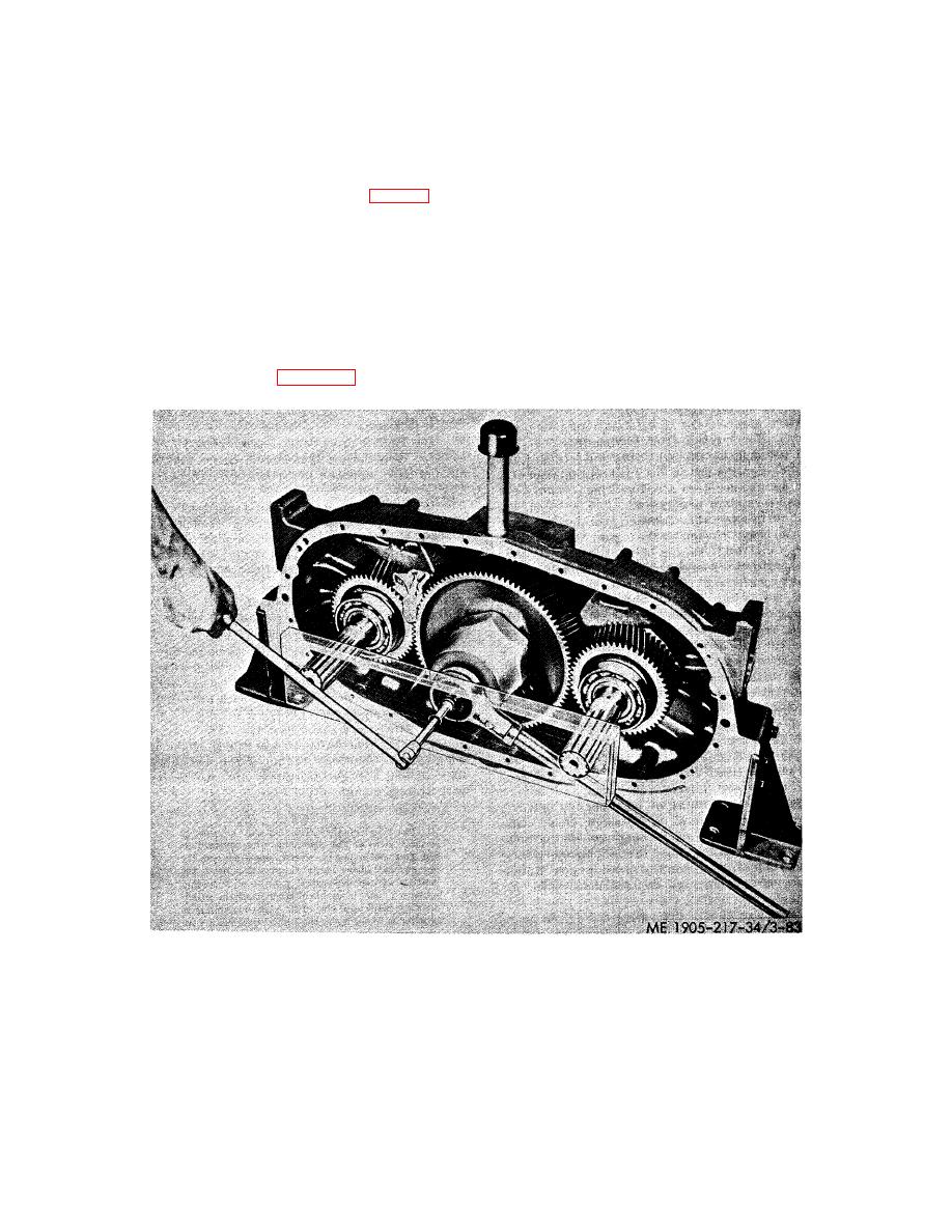
(d) Insert a spare reverse gear shaft in each power drive gear. Place a supporting member,
with two 2 inch holes having centers 19- 1/8 inches apart, and a 1 inch hole centered between the two 2
inch holes, over the splined end of the two drive shafts and push it against the torque multiplier wrench,
as shown in figure 3-83, to prevent the drive gears from spreading.
Figure 3-83. Removing lock nut from power driven shaft.
(e) Insert a 1/2 inch square drive short extension through the 1 inch hole in the sup- porting
wrench; then, attach a flex handle to the short extension. With the transfer gear housing held in a fixed
position and a clean cloth between the gear teeth, loosen the driven gear lock nut by turning the nut
counterclockwise.
3-113
|
||
|
||


