
| Tweet |

Custom Search
|
|

|
||
 TM 55-1905-217-34
bearing bores in the adapter plate. Push the assembly forward over the dowel pins and against the adapter plate gasket.
(7) Install the gear housing to the adapter plate. Tighten the bolts to 30-35 ft-lb torque.
(8) Remove the sling, chain hoist and eye-bolts from transfer gear housing.
(9) Attach a sling and chain hoist to the lifting bracket at the top of each engine flywheel housing. Lift the rear of the
engines just enough to permit the removal of the blocking from beneath the flywheel housing.
(10) Lower the unit so it rests on the side rails. Aline the bolt holes in the side rail with the bolt holes in the flywheel and
transfer gear housings. Then, install the two side rails to the flywheel housing bolts with lock washers on each engine, and
the four side rails to gear housing bolts with lock washers at each side of the gear housing.
(11) Tighten the side rail to the flywheel housing and gear housing bolts to 71-75 ft-lb torque.
(12) Tighten the front support bracket to side rail bolt nuts to 83-93 ft-lb torque. 3-24. Crankshaft Rear Oil Seal
a. Removal.
(1)
Remove the transfer gear assembly (para 3-23).
(2)
Remove flywheel housing (para 3-23).
(3)
Support the flywheel housing on its rear face on wood blocks.
(4)
Drive the oil seal out and clean the seal bore in the flywheel housing.
b. Inspection and Repair.
(1) Inspect the seal for defects and signs of deterioration.
(2) Replace a defective rear oil seal.
c. Installation.
(1) Support the inner face of the flywheel housing on a flat surface.
CAUTION
There is a plastic coating on the outside diameter of the oil seal. Do not remove this coating.
(2) Position the new seal with the lip turned toward the inner face of the housing.
(3) Drive the seal into the housing with installer J 9727 and handle J 3154-1 until it is seated against the
shoulder in the housing bore.
CAUTION
Do not attempt to install this seal with other than prescribed tools since improper
installation may allow leaks or damage to crankshaft.
3-25. Main Bearing Caps and Shells
a. Removal. (Crankshaft in Place)
(1) Drain cooling and lubricating systems (TM 55-1905-217-12, para 3-2).
(2) Remove oil pump (para 3-11).
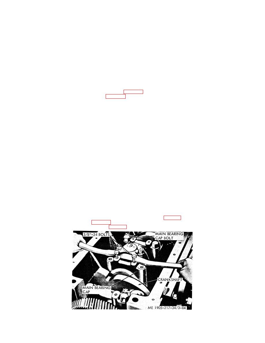
(3) Remove main bearing caps (fig. 3-84)
Figure 3-84. Main bearing cap, removal.
3-115
|
||
|
||


