
| Tweet |

Custom Search
|
|

|
||
 TM 55-1905-217-34
NOTE
Do not disassemble the cover band assembly.
(2) Remove four commutator end bracket bolts (19) from commutator end bearing assembly (1).
(3) Tap end bearing assembly (1) with a rawhide mallet to loosen and remove this assembly from frame
and field assembly (3).
(4) Remove twelve drive housing bolts (11) holding frame and field assembly (3) to motor drive housing
assembly (10) and remove frame and field assembly.
c. Disassembly of Drive Housing Assembly. To disassemble the drive housing, it must be removed from
middle bearing assembly (6, fig. 4-8) and Bendix drive assembly (9) as follows:
(1) Remove locking wire and remove six middle bearing attaching screws (15) which secure middle
bearing assembly (6) to drive housing assembly (10).
(2) Remove middle bearing assembly (6) with Bendix drive assembly (9) and armature assembly (5)
from drive housing assembly (10).
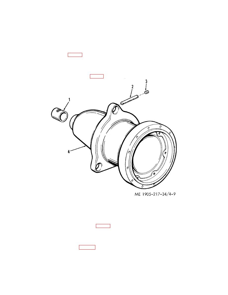
(3) Remove drive end pipe plug (3, fig. 4-9) and drive end lubricating wick (2) from housing (4).
Figure 4-9. Motor drive housing-exploded view
(4) The drive end housing sleeve bearing (1) may now be pressed from the housing. Use suitable arbor
press and rod for this purpose.
NOTE
Do not remove the bearing unless replacement is necessary.
d. Disassembly of Middle Bearing Assembly.
(1) Remove middle bearing gasket (7, fig. 4-8).
(2) Move retaining wire to one side and loosen setscrew holding Bendix drive assembly (9) to armature
assembly (5).
(3) Pull Bendix drive assembly (9) from armature assembly.
(4) Remove middle bearing assembly (6), spacer washer (8) and brake shoe (20) from armature shaft.
(5) Remove oil hole plug (1, fig. 4-10).
4-16
|
||
|
||


