
| Tweet |

Custom Search
|
|

|
||
 TM 55-1905-217-34
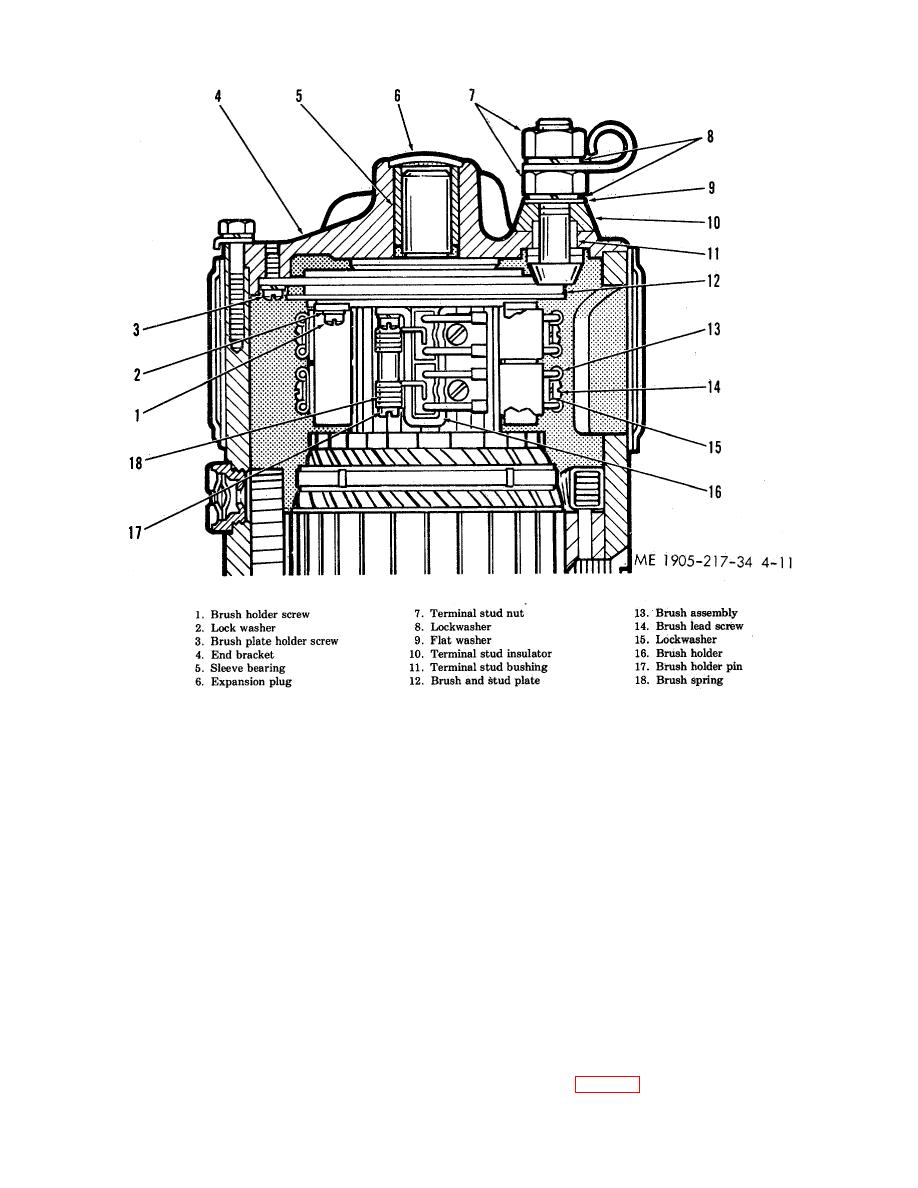
Figure 4-11. Commutator end bearing assembly-cross-section view.
(2) Two of the brush holders may be removed in the following manner:
(a) Remove brush holder screws (1), lockwashers (2), brush holder pins (17) and brush springs
(18).
(b) Remove brush holders (16) and brush holder spacer plates from brush and stud plate (12).
(3) The other two brush holders may be removed in the following manner:
(a) Remove brush holder screws (3) and lockwashers, brush holder pins (17) and brush springs
(18).
(b) Remove brush holders (16) and brush holder spacer plates from brush and stud plate (12).
(4) Remove terminal stud nuts (7), lock- washers (8), plain washer (9), terminal stud insulator (10), and
insulated terminal stud bushing (11) as required.
(5) Remove brush plate assembly from commutator end bracket (4).
(6) If necessary, brush and stud plate (12) may be separated from the brush plate in order to replace
defective parts.
(7) To replace commutator end bearing (5), remove commutator end expansion plug (6) and
commutator end pipe plug and wick. Press sleeve bearing (5) from bracket (4).
NOTE
Do not remove plug (6) or bearing (5) unless replacement is necessary.
f. Disassembly of Frame and Field Assembly.
NOTE
Do not remove pole shoes or field coil assemblies unless defective parts make
disassembly necessary.
(1) Unsolder field coil assembly leads from field terminal studs (5, fig. 4-12).
4-18
|
||
|
||


