
| Tweet |

Custom Search
|
|

|
||
 TM 55-1905-217-34
(2) Scribe marks on the mounting plate (43) and the pump body (24) prior to disassembly to ensure their correct reassembly.
Remove the three bolts (4) and lock washers and separate the mounting plate (43) from the pump. Remove and
discard the gasket (6). Withdraw the bearing retainer (41) from the pump body. Remove and discard the second
gasket (6).
(3) Remove the shaft (8) , bearings (11) , (9) , (7) and fiber washer (10) as an assembly from the pump body.
(4) If inspection reveals the bearings and fiber washer are worn excessively remove them from the pumpshaft for
replacement by new parts.
(5) Remove the pump piston (17) and the retaining spring (37) from the pump body.
(6) Remove the relief valve plug (15) , gasket (14) , spring (13) , and spring seat (12).
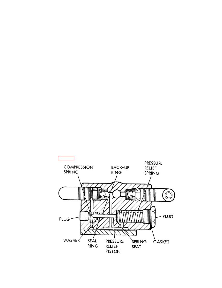
(7) Remove the retaining plug (33) , compression spring (34) , pressure relief piston (35) , washer (40) ,
seal ring (39) and backup ring (38).
(8) Remove the pump outlet elbow (32) , spacer (31) , retainer (30) , and baffle (29). The helical
spring (28) , ball (36) and cage (27) may then be removed as an assembly. Remove the baffle (26).
DO NOT separate the helical spring (28) and ball (36) from the cage. If the check valve on either
side of the pump is defective, replace the complete check valve assembly.
(9) Remove the pump inlet elbow (18) and the check valve retainer (19). Then remove the cage (20) ,
ball (21) , and spring (22) as an assembly. Remove the baffle (23). DO NOT separate the spring
(22) and the ball (21) from the cage.
(10) The pump-to-reservoir return elbow (25) and plug (16) may be removed, if necessary, to clean the
pump body.
(11) Remove the oil seal (42) from the bearing retainer (41) , if the seal is worn or damaged.
c. Cleaning, Inspection, and Repair.
(1) Clean all parts with a solvent (FED. SPEC. PD-680) , and dry thoroughly.
(2) Inspect bearing surfaces for excessive wear and scoring. Replace defective parts.
d. Reassembly.
(1) Insert the spring seat (12) and pressure relief spring (13) and lock them in place with a gasket (14)
and plug (15).
(2) Slide a new backup ring (38) , new seal ring (39) and washer (40) onto the end of the pressure relief
piston (35) , opposite the flat end. DO NOT slide the seal across the groove in the piston.
(3) Coat the backup ring and seal ring liberally with hydraulic fluid. Then insert the relief piston
assembly into the pump body (24) , the flat end of the piston first, using J 7192. Apply manual force
to the tool in order to gradually work the back-up ring and seal ring into the counterbore around the
relief piston. Care must be taken to avoid cutting the seal ring as it is worked into place. Refer to
figures 4-18 and 4-19.
ME 1905-217-34/4-18
Figure 4-18. Pump pressure relief piston assembly, cross-section view.
4-30
|
||
|
||


