| Tweet |

Custom Search
|
|

|
||
 TM 55-1905-217-34
and does not generally need replacement. If this is replaced it should be pressed into counter-bore so that the lip
is directed away from the unit. Place the mounting plate subassembly over spool shaft and slide down into place over
cap locator bushing smoothly so that seals will not be disrupted in assembly. Aline bolt holes with tapped holes. Be
certain that the mounting plate rests fairly flush against end of housing assembly so that the cap locator bushing is not
cocked. Install four mounting plate cap screws. Tighten these evenly and gradually to a torque setting of 250 inch
pounds.
(8) Reposition housing in vise (14 hole surface up) and clamp across the edges of the mounting plate. Check to
insure that spool and sleeve are flush or slightly below the 14 hole surface of the housing. Clean the upper surface of the
housing by wiping with the back of a clean hand or the butt of the thumb. Clean each of the flat surfaces of the meter
section parts as it is ready for assembly in a similar way.
(9) Place the plate (3) over the housing assembly so the bolt holes in the plate align with the tapped holes in the
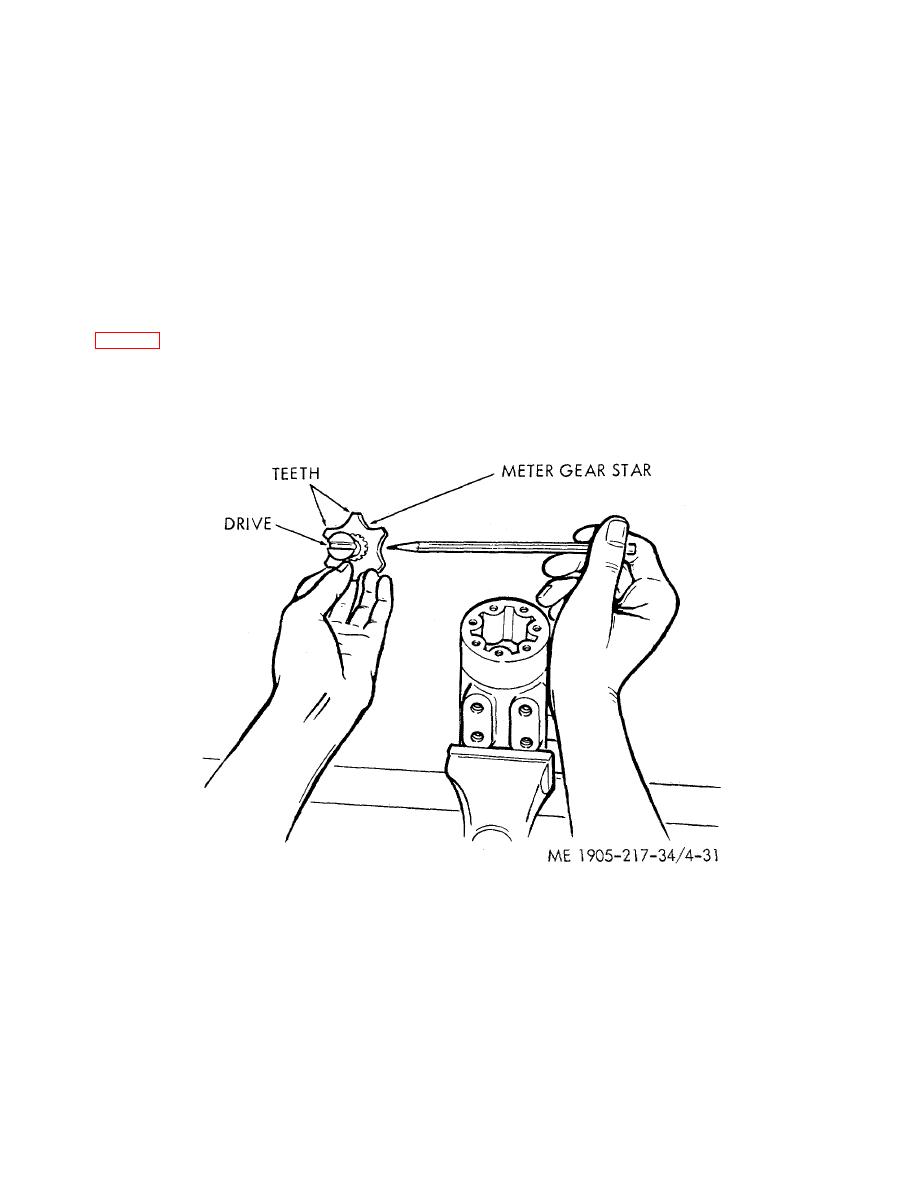
housing. Place the meter gear ring (4) on the assembly so the bolt holes aline. Place the splined end of the drive within
the meter gear star so that the slot at the control end of the drive is in alignment with the valleys between the meter gear
teeth (fig. 4-31). Push the splined end of the drive through the gear so that the spline extends about one half its length
beyond the meter gear star and hold it in this position while installing into the unit. Note the position or direction of the
centering pin within the unit. Enter the meter gear star into the meter gear ring and wiggle the parts slowly in position so
that the drive does not become disengaged from the meter gear star. Hold the plate and meter gear ring in position on
the assembly while the star is being installed. Rotate the meter gear star slightly to bring the cross slot of the drive into
engagement with the centering -pin and the splined end of the drive will drop down against the plate.
Figure 4-31. Drive and meter gear star.
CAUTION
Alinement of the cross slot in the drive with valleys between the teeth of the meter gear
star determines proper valve timing of the unit. There are 12 teeth on the spline and 6
pump teeth on the star. Alinement is exactly right in 6 positions and exactly wrong in 6
positions. If the parts slip out of position during this part of the assembly, repeat until
you are certain that correct alinement is obtained.
(10) Place the spacer (2) in position within the end of the meter gear star. If the spacer does not drop flush with
the gear surface, the drive has not properly engaged the centering pin- RECHECK. Place the meter end cap over
the
4-48
|
||
 |
||