
| Tweet |

Custom Search
|
|

|
||
 TM 55-1905-217-34
assembly and install two cap screws, finger tight, to maintain alignment of the parts. Install all seven cap screws and
bring them gradually and evenly to 150 inch pounds torque.
(11) Check the condition of the column assembly, clean it, and replace on the unit with two cap screws oriented as
before. Rotate the steering shaft while bringing the surfaces into contact to allow splines to engage; Tighten cap screws
to 280 inch pounds.
e. Installation. Install the helm control unit(TM 55-1905-217-12, para 4-82).
4-14. Steering System Valves
a. General.
(1) Refer to Operator and Organizational Maintenance Manual TM 55-1905-217-12 for diagram of steering
hydraulic system.
(2) Malfunctioning of relief valves, flow control valves, overcenter valves, and counter- balance valves can
normally be remedied by cleaning, adjustment, or replacing seals. If inspection shows worn seats or other physical
damage, replace the valve.
b. Steering System Valves Removal - Hulls 8500-8519.
(1) Overcenter valve removal.
(a) This valve is located in the center: of the engine room, near the aft bulkhead, just below the deck. It is connected
into both lines between helm unit and steering cylinder valves (four connections).
(b) Drain steering hydraulic system to a level below the valve. Refer to TM 55-1905-217- 12, figures 1-9 and 1-10.
(c) Disconnect tube connections and remove valve.
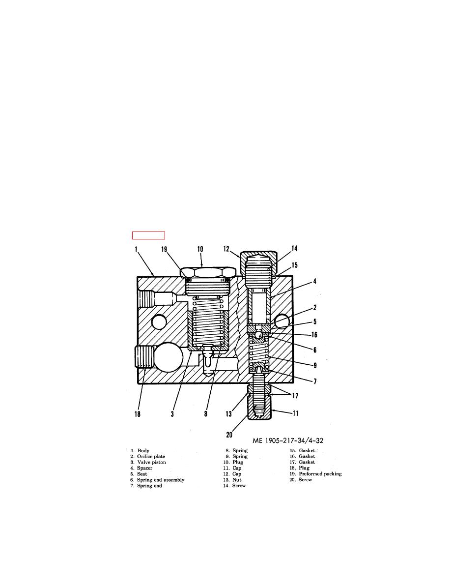
(2) Relief valve removal (fig. 4-32).
Figure 4-32. Steering system relief valve, cross -section view.
4-49
|
||
|
||


