
| Tweet |

Custom Search
|
|

|
||
 TM 55-1905-217-34
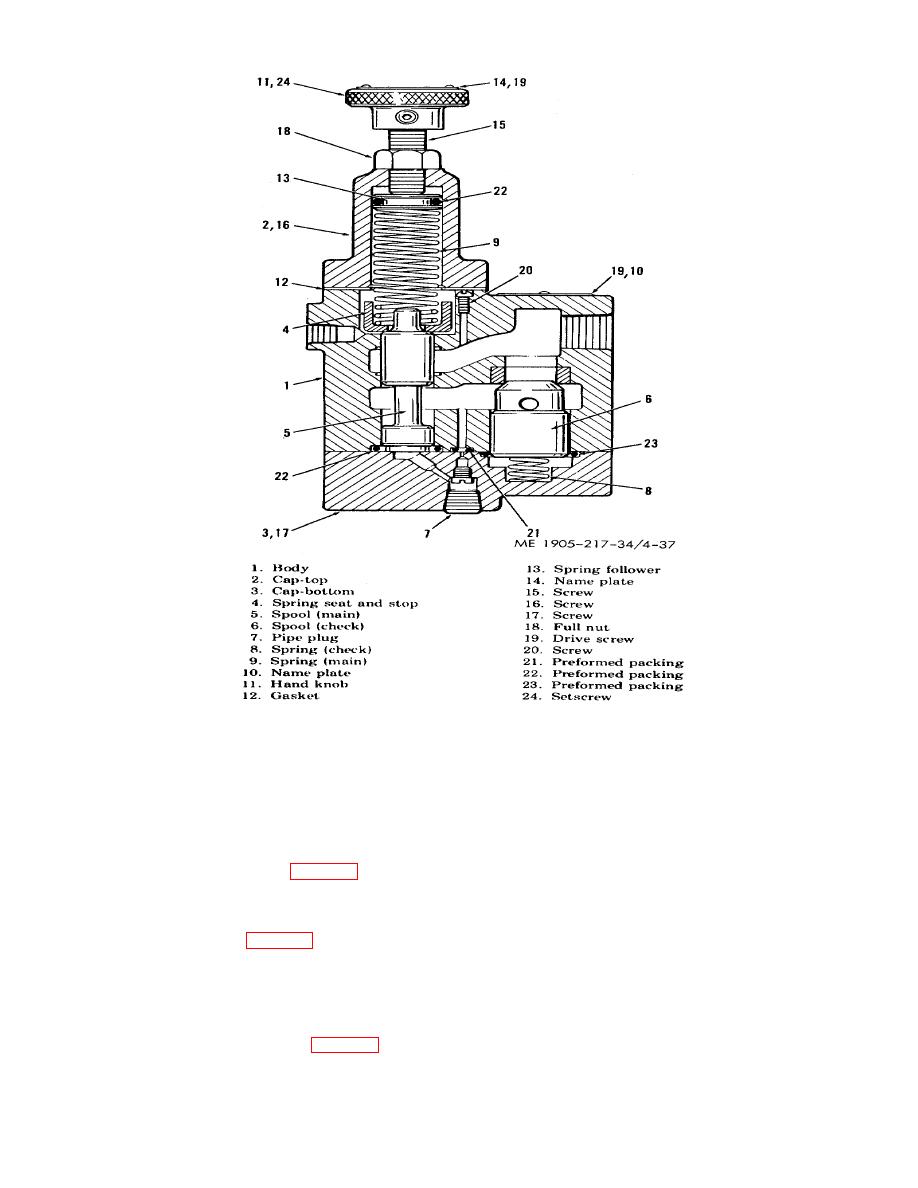
Figure 4-37. Steering system counter balance value (hulls 8520-8560 and 8580-8618).
f. Steering System Valves, Installation.
(1) Install valves in reverse order of removal.
(2) Refill tanks and lines, (TM 55-1905-217-12, para 4-76).
g. Steering System Valves, Adjustment-Hull Nos. 8520 through 8560 and 8580 through 8618.
(1) Flow Divider valve (fig. 4-36). The flow divider valve is adjusted to a 2 gpm flow at 1050 psi. The
pressure is adjusted by adding or removing shims (16). Three sizes of shims are used--.042 inch thick effects
pressure approximately 300 psi; .021 inch thick effects pressure approximately 105 psi; and .010 inch thick
which effects pressure approximately 75 psi.
(2) Relief Valve (fig. 4-35). The relief valve can be adjusted at first or second echelon of maintenance.
For Hulls 8500-8519, adjust by putting the helm hardover in either direction with engines running (1 pump only
supplying system). Remove cap from the relief valve, loosen nut, and back off screw until it no longer bears on
the spring. Hold the helm in a hardover position and slowly turn down screw until the pressure gage reads
1,500 psi indicating that the valve is relieving at 1,500 psi. Lock this setting with nut and replace cap. For Hulls
8520-8539, valve maximum pressure setting is 1050 psi.
(3) Counterbalance Valve (fig. 4-37). The counterbalance valve is adjusted to 1,000 psi by turning the
control knob.
4-54
|
||
|
||


