
| Tweet |

Custom Search
|
|

|
||
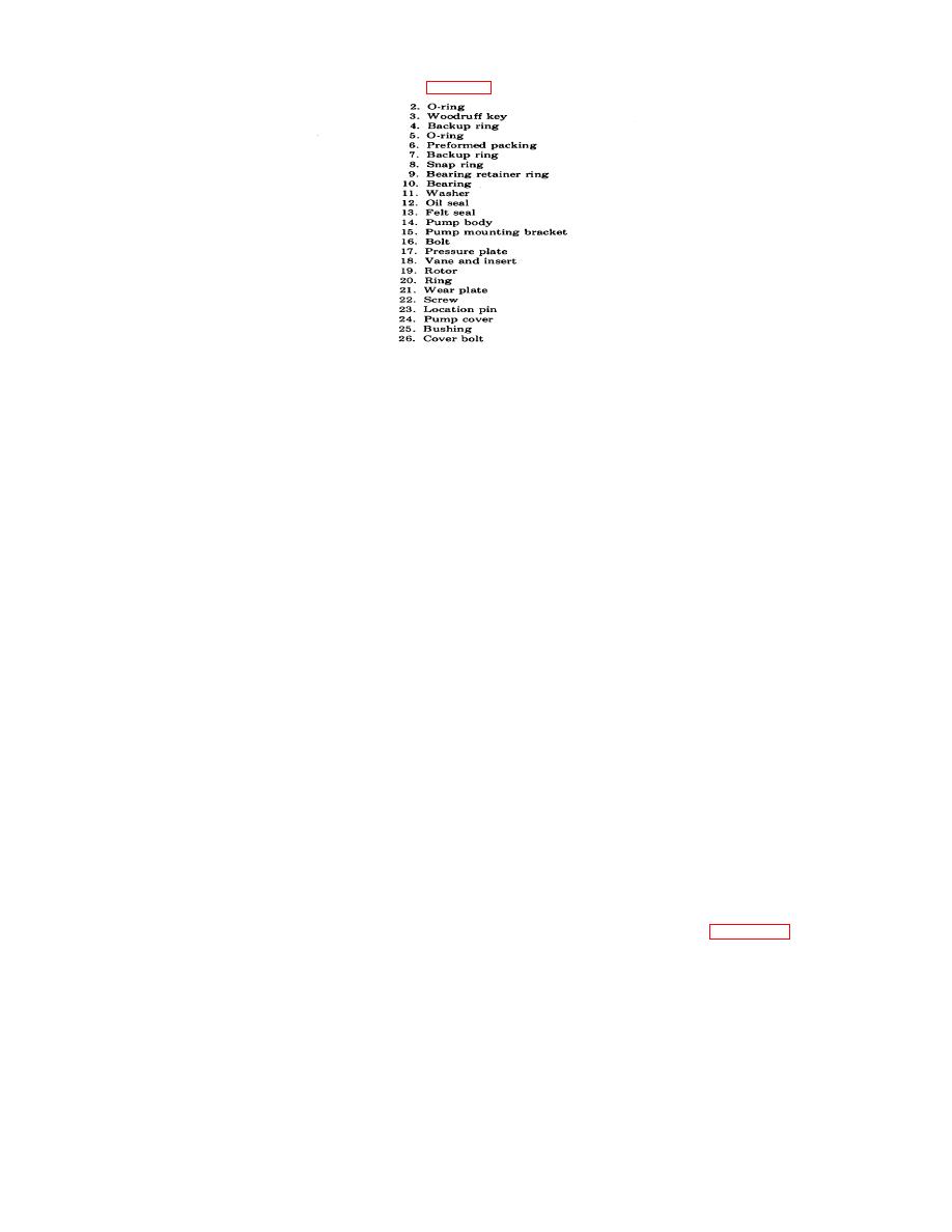 TM 55-1905-217-34
Key to figure 4-47
(2) Grasp the pump cartridge (inner assembly) and while turning, pull it from the drive shaft. Loosening of the
pump cartridge can be accomplished by prying under the flats of the ring with two screw-drivers.
(3) Remove large O-ring (2) from recess in body.
(4) Remove O-rings (5, 6) and backup rings (4,7) from hub and outside diameter of pressure plate (17).
(5) Remove two screws (22) from face of wear plate (21). Lift wear plate from locating pins (23) and remove pins.
(6) Remove ring (20) from around the rotor (19).
(7) Remove vanes and inserts (18) from rotor and remove rotor from the pressure plate.
(8) Wash and dry all cartridge parts.
(9) Inspect surfaces of wear plate, pressure plate, ring and rotor for scoring and excessive wear. Light scoring
may carefully be stoned or lapped. Discard parts that are heavily scored. Check edges of vanes for wear. Vanes shall not
have excessive play in rotor slots or burrs on edges. Inspect inside diameter of bushing (25). Remove bushing if wear or
scoring is evident. If wear plate is to be replaced, do not remove bushing as a new plate comes with bushing inserted.
(10) Lift out shaft key (3) from its seat in shaft. Remove bearing retaining ring (9) and fully remove drive shaft and
bearing (10) from body by gently tapping the keyed end of shaft with a soft hammer.
(11) Check the bearing for wear before removing it from the shaft. Rotate bearing, applying a little pressure to the
outer race, to determine whether the balls or races have become pitted, galled or cracked. Check for looseness. If in
doubt, remove bearing from shaft at the point of contact with bushing and sealing lip of shaft oil seal. If excessive scoring
or wear is noted, replace shaft.
(12) Remove washer (11) from bore in body. Using a suitable hooked tool or a drift, remove shaft oil seal (12) and
felt seal (13) from body.
d. Reassembly.
(1) Lubricate replacement parts before assembly with clean hydraulic fluid.
(2) Install a new felt seal and shaft oil seal in counterbore of body. Soak both seals thoroughly in hydraulic oil
before installing. Make sure that lipped edge of seal is toward inside of body. Use a suitable drift that will not damage the
seal during installation. Lubricate the shaft oil seal journal with petroleum jelly.
(3) Position shaft bearing in place on drive shaft, being careful not to cock the bearing. Use arbor press, support
the inner race of the bearing and press the bearing against the shoulder of the craft. Apply tape around the end of shaft to
protect the seal. Install shaft and bearing into the body until the bearing is fully seated. If necessary, gently tap the shaft
with a soft hammer.
(4) Install shaft snap ring and bearing retaining ring. Make sure that both parts are firmly seated in place.
(5) Install the shaft key at this time or after the pump has been completely reassembled.
e. Pump Cartridge Reassembly.
(1) Install O-ring and backup ring in groove on hub diameter of pressure plate. Install a backup ring and O-ring
around large step diameter of pressure plate. Make sure that smooth sides of backup rings face the sealing rings.
NOTE
Back-up rings must always be installed away from the pressure chamber. See figure 4-47.
(2) Position large O-ring in recess in body. Use petroleum jelly to hold O-ring in position during assembly of pump
cartridge.
NOTE
Direction of rotation is designated as viewed from shaft end of pump. R. H. rotation is
clockwise, I,. H. rotation is counterclockwise.
(3) Place rotor on pressure plate with arrow pointing in desired direction of rotation. Install inserts in vanes and
position both parts in rotor slots. The sharp edges of the vanes must be toward direction of rotation.
(4) Install locating pins in pressure plate. Install ring over locating pins against pressure
4-75
|
||
|
||


