
| Tweet |

Custom Search
|
|
|
|
||

|
||
 TM 55-1905-217-34
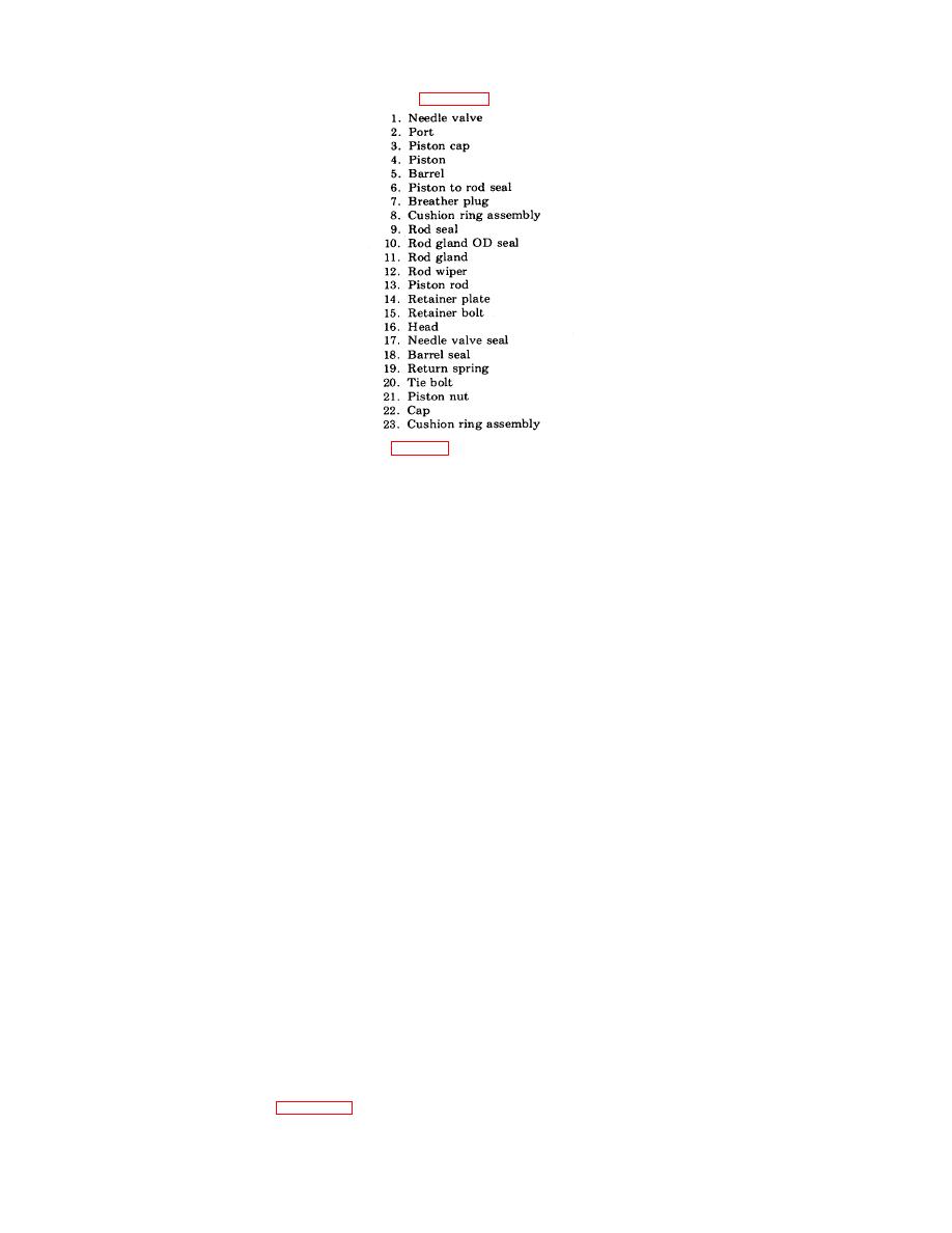
Key to figure 4-54.
(1)
Remove the four retainer plate bolts (15, fig. 4-54) and retainer plate (14).
(2)
Remove the rod gland (11) and seals (10).
(3)
Remove tie bolt nuts (21) and end cap (22).
(4)
Remove barrel (5) from head (16) with piston (4) and piston rod inside.
(5)
Pull piston rod (13) assembly from barrel.
NOTE
Do not remove piston from piston rod unless parts are damaged or definite leakage has occurred past
the piston. If piston is removed from the piston rod, the piston nut must be torqued to 55 ft. lbs. on
reassembly.
d. Cleaning, Inspection, and Repair.
(1) Wash all parts thoroughly in solvent, FED. SPEC. PD-680) type I, and place them on a clean surface for inspection.
(2) Discard old seals, wiper, piston cups and glands.
(3) Check cylinder, piston and piston rod for scores and burrs. Carefully remove burrs by light stoning or lapping. If scoring
appears to be excessive, replace the defective parts.
e. Reassembly.
(1) Lubricate replacement parts before assembly with clean hydraulic fluid.
(2) Place piston in groove nearest the rod end with cupped side facing the rod end. Enter the piston and rod assembly into the
barrel until the empty groove is exposed on the opposite end. Place the cup in the exposed groove with cupped side facing away from the
rod end. Pull the rod and the piston into the barrel.
(3) Reassemble the barrel (5) to the head (16).
(4) Replace tie bolt nuts (21).
(5) Replace cap (22).
(6) Torque tie rods to 15 ft lbs each; tightened a little at a time, alternately with opposite tie rods until correct torque is reached.
f. Gland and Seal Replacement. Rod gland, rod seal, rod wiper and gland OD seal shall be replaced as follows:
(1) Extend piston rod 1/4 of stroke.
(2) Remove pressure from system.
(3) Support rod and cylinder to prevent damage when rod gland is removed.
(4) Remove rod and accessories.
(5) Remove burrs from rod lats.
(6) Remove retainer bolts (15).
(7) Remove retainer plate (14).
(8) Remove rod gland (11) by prying with screwdriver in pryout groove.
(9) Clean all parts.
(10) Lubricate parts to be replaced with hydraulic fluid.
(11) Push or tap rod gland (11) back into head being careful not to damage rod seals (9, 10).
(12) Replace retainer plate (14) and retainer bolts (15).
(13) Torque retainer bolts to 15 ft lbs.
g. Installation. Install the ramp locking cylinders (TM 55-1905-217-12, para 4-97).
4-25. Ramp Locking System Two-Way Selector Valve (Hulls 8540-8560 and 8580-8618).
a. General. Refer to TM 55-1905-217-12, para 4-98, for a description and location of the selector valve.
b. Removal. Remove the two-way selector valve (TM 55-1905-217-12, para 4-98).
4-85
|
||
|
||


