
| Tweet |

Custom Search
|
|

|
||
 TM 55-1905-219-14-10
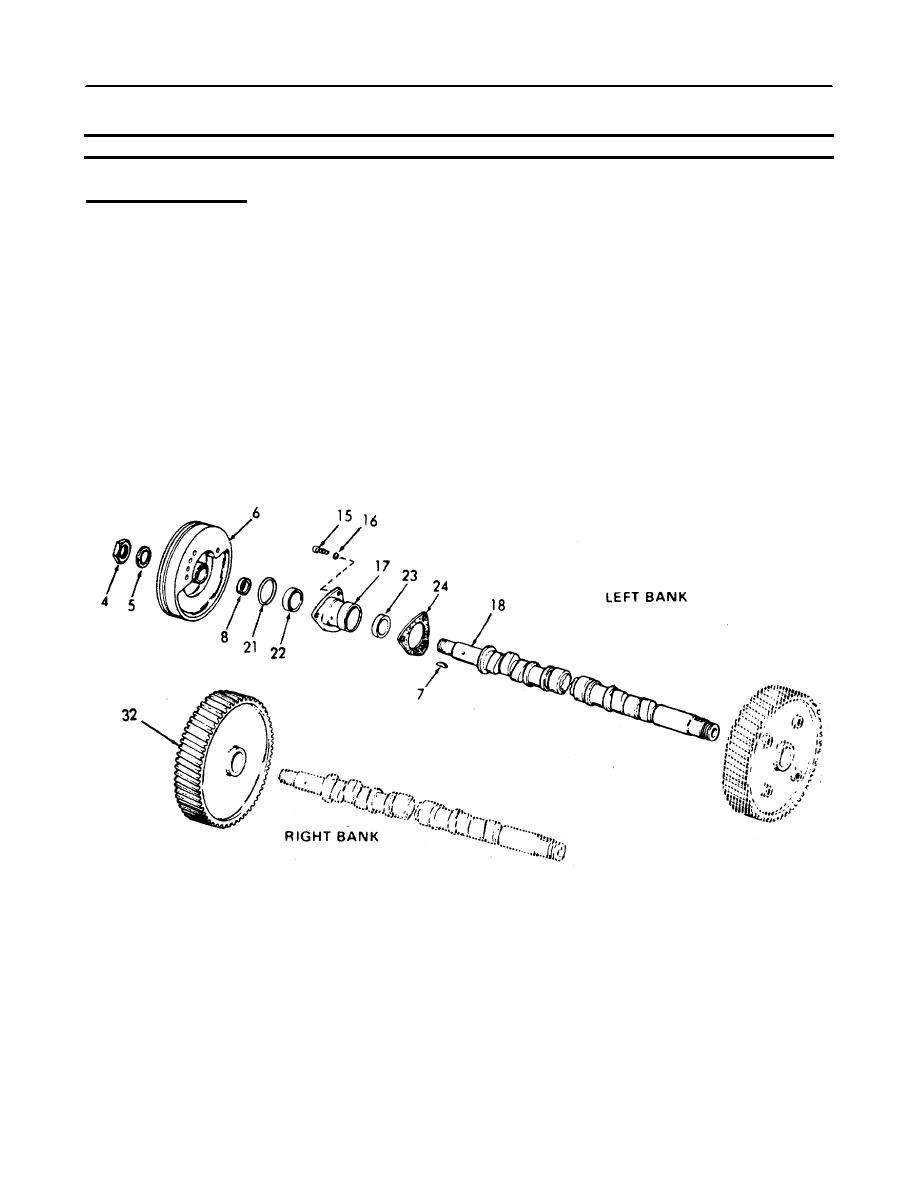
5-19.1. CAMSHAFT ASSEMBLY AND GEAR TRAIN - MAINTENANCE INSTRUCTIONS (Continued).
LOCATION
ITEM
ACTION
REMARKS
INSTALLATION (Cont)
k.
Front
Install on left bank.
balance
pulley
(6)
l. Right bank
Install.
gear (32)
m. Internal
1 Install on both ends
tooth
of each camshaft.
(5), and
2. Wedge a clean cloth
nuts (4)
between the camshaft
gears to prevent
rotation.
3. Tighten nut to 300-325
lb-ft (406.8 - 440.7
Nm) torque.
5-341
|
||
|
||


