
| Tweet |

Custom Search
|
|

|
||
 TM 55-1905-219-14-10
5-43. CYLINDER BLOCK-MAINTENANCE INSTRUCTIONS (Continued).
LOCATION
ITEM
ACTION
REMARKS
INSPECT (Cont.)
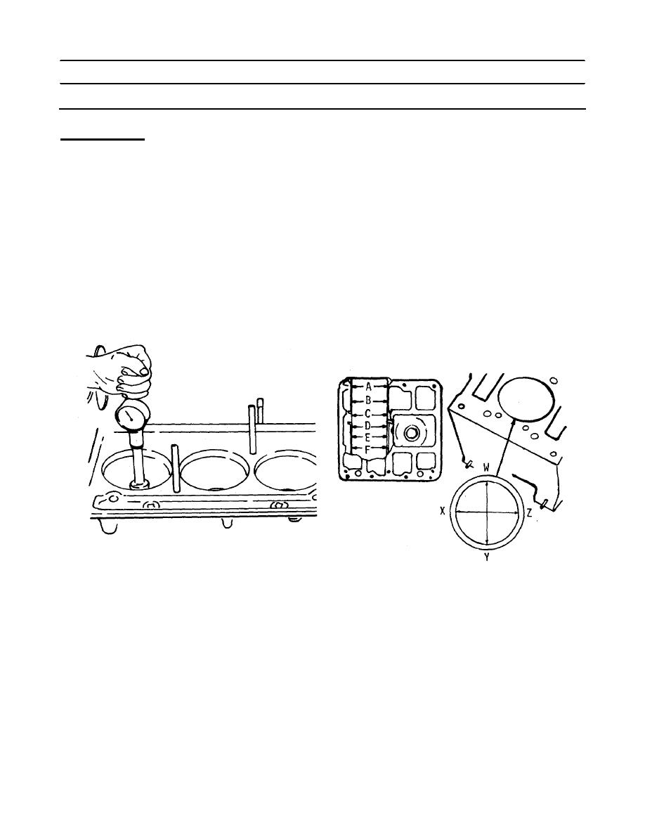
d. Check the cylinder block bores:
(1) Visually check the contact area as revealed by the hone surface. There must not
d
be any low spots which are larger in area than a half dollar.
(2) Measure the entire bore of each cylinder with cylinder bore gage J5347 which has
a dial indi- cator calibrated in .0001 inch increments. The standard block bore is
4.6260 inch to 4.6270 inch.
(3) First, place the bore gage in the master ring gage J8386-01 which has an I.D. of
4.6270 inch and set the dial to zero. Next, rotate the dial clockwise .0005 inch to
give a zero dial indicator setting of 4.6265 inch. Take measurements on the
cleaned-up surface only at positions A, B, C, D, E, and F in-the bore on axes 45
apart. Read the measurements from the zero mark on the gage.
5-624
|
||
|
||


