
| Tweet |

Custom Search
|
|

|
||
 TM 55-1905-219-14-11
5-117. SHIP'S COURSE INDICATOR - MAINTENANCE INSTRUCTIONS (Continued).
(c)
De-energize the indicator servo and dial assembly by disconnecting the plug with its cable from the case.
Inspect assembly S' for excessive gear train or bearing friction, loose clamps, loose terminal connections, loose screws,
and for any signs of defective electronic components or wiring. If the gear train is binding, clean the gears or
disassemble the gear train and clean all gears and lubricate all bearings. Replace any defective bearing or gears.
(d)
Gear train disassembly instructions are presented in step 1.
(e)
If inspection and mechanical tests show the rotating components to be mechanically operative proceed
as follows to check that they are electrically operative. Reconnect the electrical plug to its other half in the case.
(f)
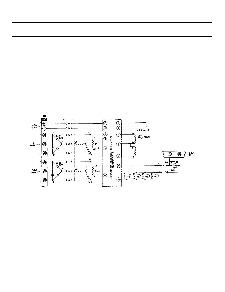
In all servo-driven indicators, under normal operation when the indicator is at rest the control field
voltage across terminals 2 and 4 of the indicator servomotor should be below 2 rms volts. Fixed-field excitation
(terminals 1 and 3) to 60-cps motors to 90 rms volts and to 400-cps motors is 45 rms volts.
(g)
Check continuity of each winding in a rotating component as follows. First remove all power and synchro
signals from the indicator. Disconnect leads to a winding, and then measuring the resistance of the winding on a scale
indicating in the 100's of ohms. Replace any unit with a shorted or open winding. (See step 4).
5-1317
|
||
|
||


