
| Tweet |

Custom Search
|
|

|
||
 TM 55-1905-219-14-4
3-53.
PROPELLER SHAFTS - MAINTENANCE INSTRUCTIONS (Continued).
LOCATION
ITEM
ACTION
REMARKS
ADJUSTMENT (Cont)
NOTE (Cont)
engine. If threaded holes are provided in each of the engine mounts, jacking screws can
be used in them. The engine can be raised by screwing down, or lowered by backing off
the desired amount. Steel plates must be inserted under the jacking screws so that the
jacking screws will not damage the engine bed. Lifting can also be accomplished by the
use of properly placed jacks. Adjustable shims also are available and can simplify the
whole problem, particularly for future realignment.
(1) It will also be necessary to move the engine and gear from one side or the other on
bed to obtain horizontal alignment. This can be done with a jack placed horizontally
between the engine and the foundation. At the same time. a straight edge is laid across
the edges of the flanges at the top and side to check the parallel alignment of the
coupling edges.
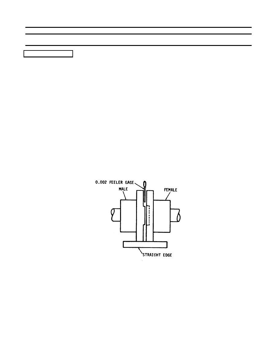
(2) As the engine and marine gear then comes into its aligned position. it will be possible
to match the male and female halves of the output flange and propeller coupling, and
prepare for bolting together. Care should be taken not to burr or mar this connection
because the fit is very critical. Place a 0. 002 inch (0. 005 cm) feeler gauge between the
flanges of the coupling.
The feeler gauge is moved (slid) completely around the
coupling.
3-981
|
||
|
||


