
| Tweet |

Custom Search
|
|

|
||
 TM 55-1905-219-14-7
3-207. HYDRAULIC CUB PUMP UNIT - BRAKE VALVE - MAINTENANCE
INSTRUCTIONS (Continued).
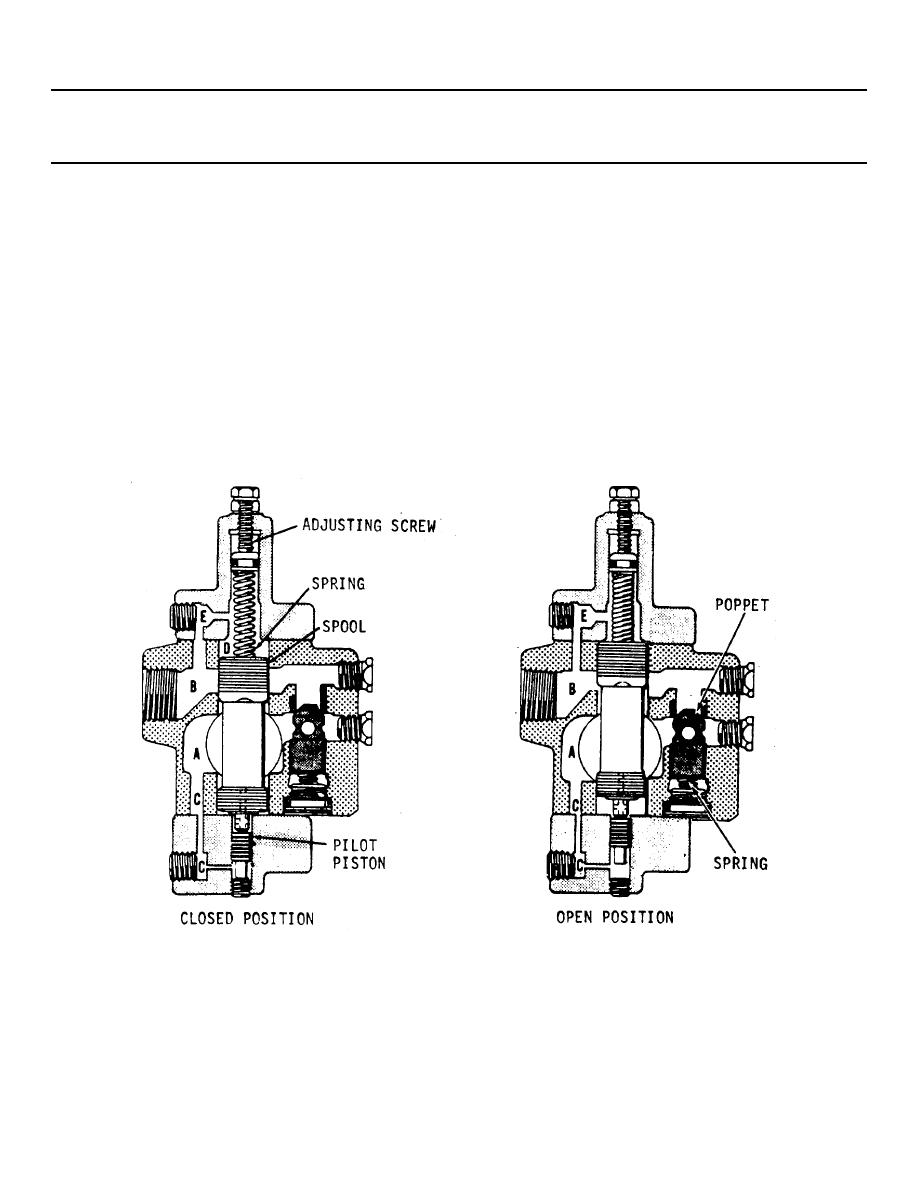
6. Fluid leakage trapped between the piston and the spool escapes through the center hole of the spool, into
spring chamber D, through drain passage E to chamber B and tank, or externally to tank depending on the position of the
top cover.
7. Operation of this valve when used with a gravity returned single acting ram is such that pump fluid passes
free flow into secondary chamber B, then through the check valve and chamber A into the ram. Pressure buildup in the
ram closes the spool.
8. When the work stroke is completed, fluid flow is diverted from the secondary port by directing the pump
delivery to tank.
9. On the return stroke, trapped fluid under pressure in the primary port holds the valve spool and check valve
closed until a small amount of fluid bleeding-off through the needle valve or orifice reduces the trapped pressure.
10.
When pressure drops below the valve setting, the spring forces the valve spool to open directing the
discharge flow through the secondary port to tank.
3-3207/(3-3208 blank)
|
||
|
||


