
| Tweet |

Custom Search
|
|

|
||
 TM 55-1905-219-14-8
4-28. AIR CONDITIONING SYSTEM - MAINTENANCE INSTRUCTIONS (Continued).
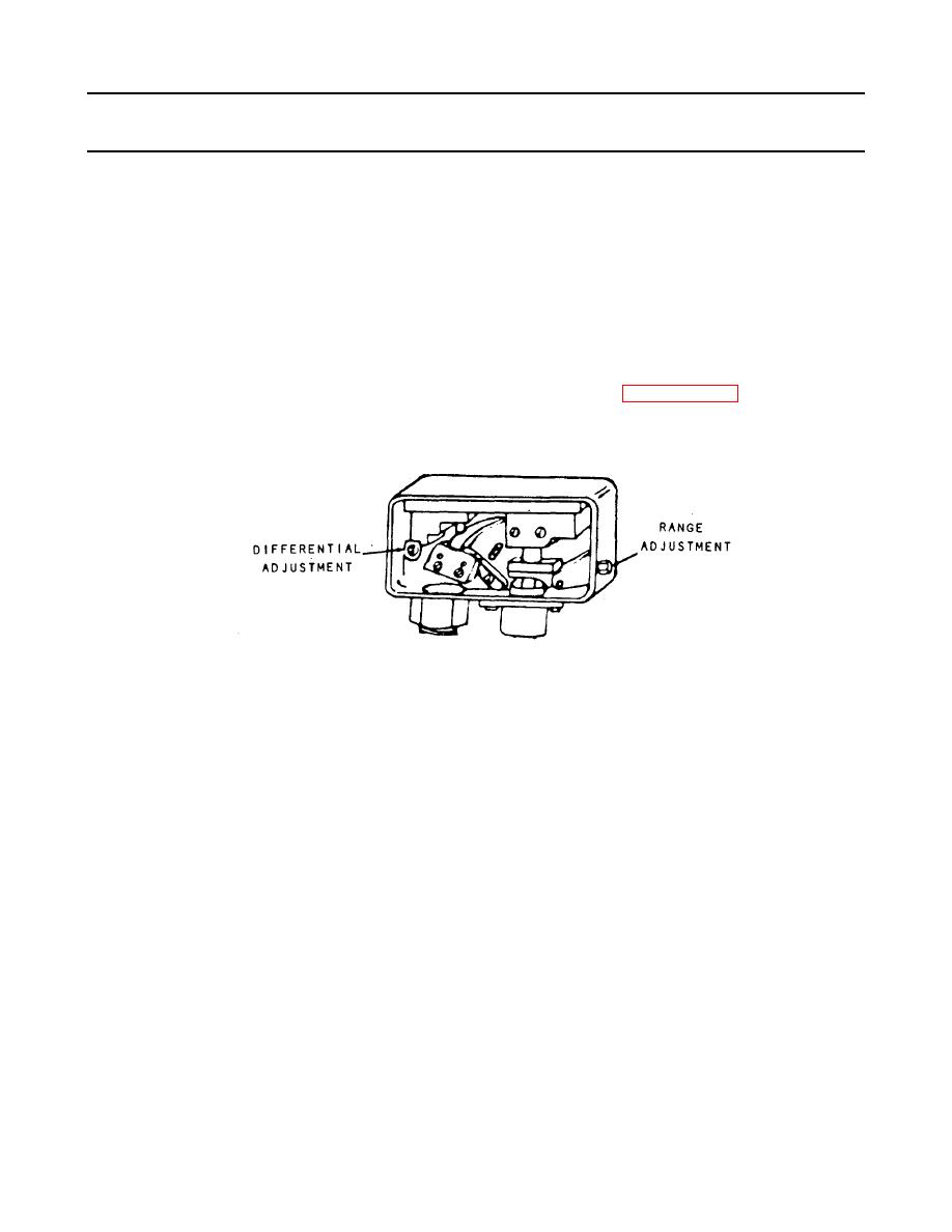
c Lower suction pressure to about 10 psi (68.9 kPa) below cut-in point. Turn range screw clockwise
until contacts open, stopping compressor. Allow suction pressure to rise to cut-in point and close
suction valve to hold it there. Turn range screw counterclockwise until contacts close, starting
compressor.
d Lower suction pressure to cut-out point and turn differential screw counterclockwise until contacts
open, stopping compressor. This fixes the cut-out point.
e Control suction pressure and check switch settings and operation.
m. Temperature Control Switches (Thermostats).
(1) The operating and safety functions of thermostats are described in paragraph 4-28a(19). The
construction and operation of the thermostat is similar to the pressure or temperature control switch shown
below.
(2) Operation.
Operating and safety thermostats cut-in and complete the electrical circuit on temperature rise. The
remote bulb of the thermostat is filled with a voltatile liquid charge and exposed to the temperature of the
medium being cooled. Changes in temperature cause changes in the pressure exerted by the remote bulb
charge on the seamless metallic bellows of the switch. On temperature rise, the pressure increases and the
bellows operates the switch mechanism to close the switch contacts and complete the electrical circuit. On
temperature fall, the pressure to the bellows decreases, the switch contacts open, and the electrical circuit is
interrupted. A permanent magnet imparts a positive snap-action to the switch contacts on both the opening and
closing cycles, preventing excessive arcing at the contacts.
4-861
|
||
|
||


