
| Tweet |

Custom Search
|
|

|
||
 TM 55-1905-220-14-1
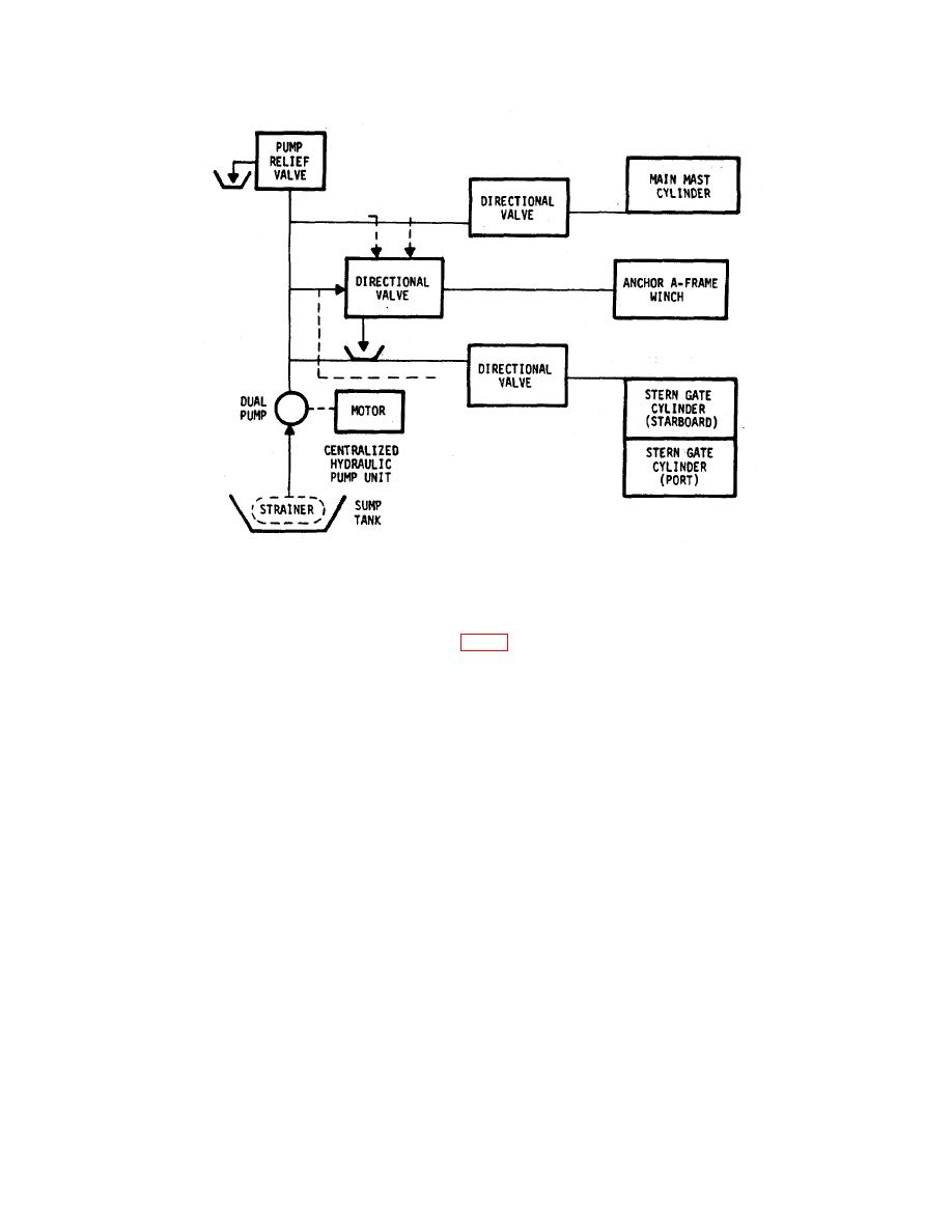
Figure 1-70. Centralized Hydraulic System (Block Diagram)
1-82. HALON SYSTEM
a. The fixed Halon Fire Extinguishing System (figure FO-15, Halon System) is located in the forward and aft engine
rooms and the flammable liquid storeroom. Modes of operation are automatic, manual, and remote manual.
(1) When there is a fire in either of the engine rooms, the amber lights flash and the horns sound to warn
occupants to clear the room immediately. An amber light will appear on the fire alarm panel in the pilothouse showing
location of fire, and if the audible alarm is set in the ON position, the pilothouse warning horn will sound. The Halon
Extinguisher will activate and put out the fire. These events will take place in the engine rooms whether the system
operates in the automatic, manual, or remote manual mode.
(2) If a fire occurs in the flammable liquids storeroom, the Halon Extinguisher will activate whether in the
automatic, manual, or remote manual mode. There is no electrical tie-in with the fire alarm panel in the pilothouse or the
engine rooms.
b. The following illustration depicts the Halon System in the automatic mode as it would operate if detecting a fire in
either of the engine rooms:
(1) Heat sensor (1) senses fire.
(2) Heated air expands and rushes down tube to control head (2).
(3) Air trips lever in control head (2) that activates the cylinder valve (3).
Change 3
1-120
|
||
|
||


