
| Tweet |

Custom Search
|
|

|
||
 TM 55-1905-220-14-10
5-4. MAIN PROPULSION ENGINE/MARINE GEAR - REMOVAL AND RUN-IN
MAINTENANCE INSTRUCTIONS (Continued).
LOCATION
ITEM
ACTION
REMARKS
ALIGNMENT (Cont)
NOTE (Cont)
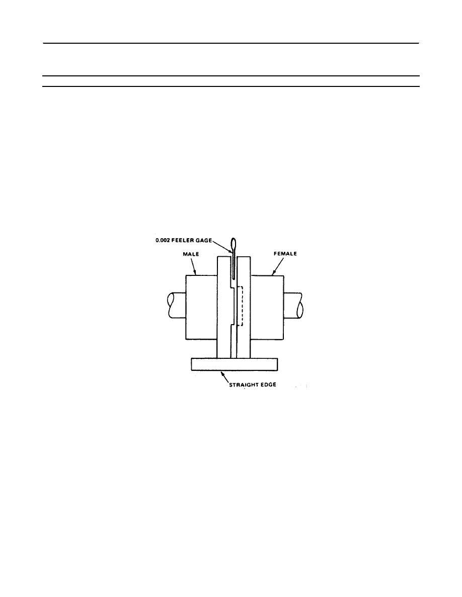
(2) As the engine and marine gear then comes
into its aligned position, it will be possible to
match the male and female halves of the output
flange and propeller coupling and prepare for
bolting together. Care should be taken not to
burr or mar this connection because the fit is
very critical. Place a 0.002 inch (0.005 cm)
feeler gauge between the flanges of the
coupling. The feeler gauge is moved (slid)
completely around the coupling.
(3) Then the marine gear flange coupling is
rotated 90, 180 and 270 degrees with the feeler
blade being moved around the flange again in
each successive position. If the alignment is
correct, the feeler gauge will fit snugly, with the
same tension, all around the flange coupling.
5- 37
|
||
|
||


