
| Tweet |

Custom Search
|
|

|
||
 TM 55-1905-220-14-10
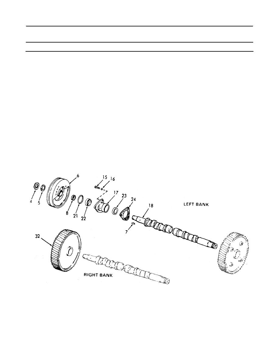
5-19.1. CAMSHAFT ASSEMBLY AND GEAR TRAIN - MAINTENANCE INSTRUCTIONS (Continued).
LOCATION
ITEM
ACTION
REMARKS
INSTALLATION (Cont)
k. Front
Install on left bank.
balance
pulley
(6)
l.
Right bank Install.
gear (32)
m. Internal
1. Install on both ends
tooth
of each camshaft.
(5), and
2. Wedge a clean cloth
nuts (4)
between the camshaft
gears to prevent
rotation.
3. Tighten nut to 300-325
lb-ft (406.8 - 440.7
Nm) torque.
5-341
|
||
|
||


